background image

Installing the Switch

5

Powering On the Switch

1.

Plug the power cord into the power socket on the rear of the switch, and the 
other end into a power outlet.

2.

Check the LED marked Power on the front panel to see if it is on. The unit will 
automatically select the setting that matches the connected input voltage. 
Therefore, no additional adjustments are necessary when connecting it to any 
input voltage within the range marked on the rear panel.

3.

The switch performs a self-diagnostic test upon power-on. (Note that this test 
takes several minutes to complete.) 

Note:

The unit supports a “hot remove” feature which permits you to connect or 
disconnect twisted-pair or fiber cables without powering off the switch and without 
disrupting the operation of the devices attached to the switch. 

Verifying Port Status 

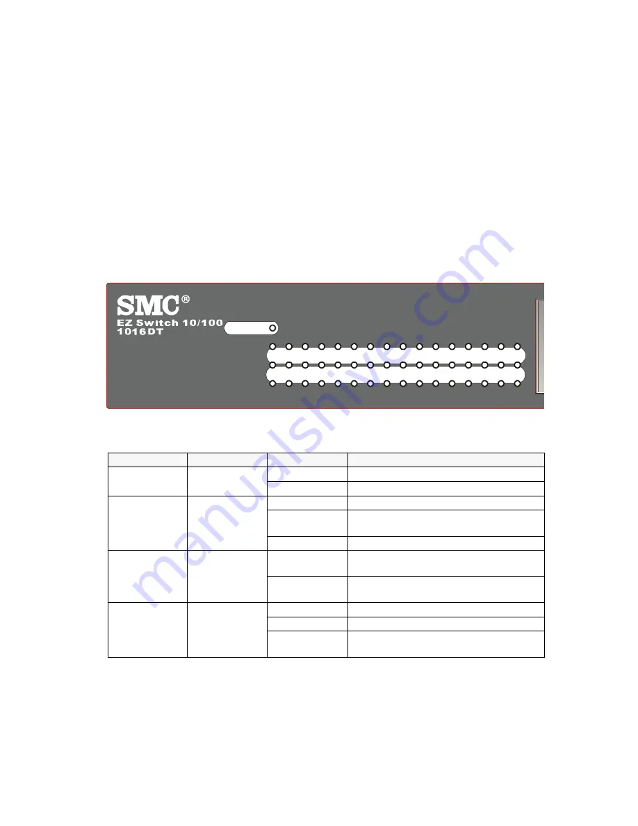
Check each connection by viewing the port indicators shown in the following table.

Label

Color

Activity

Description

Power

Green

On

Power is supplied to the switch.

Off

Power is disconnected.

Link/Act

Green

On

The network port is connected

Blinking

Packet transmission or reception is 

occurring on the port.

Off

The network port is not connected.

10/100M

Green

On

A valid 100Mbps link is established on 

the port.

Off

A valid 10Mbps link is established on 

the port.

FDX/Col

Green

On

The port operates in full-duplex mode.

Off

The port operates in half-duplex mode.

Blinking

There’re collisions when packet 

transfers.

1

2

3

4

5

6

7

8

9 10 11 12 13 14 15 16

Link/Act

10/100M

FDX/COL

POWER


Summary of Contents for SMCEZNET-16SW

Page 1: ......

Page 2: ......

Page 3: ...38 Tesla Irvine CA 92618 Phone 949 679 8000 EZ Switch 10 100 User Guide From SMC EZ line of low cost workgroup LAN solutions Aug 2003 Pub 150000024200B R01...

Page 4: ...ense is granted by implication or oth erwise under any patent or patent rights of SMC SMC reserves the right to change specifications at any time without notice Copyright 2003 by 38 Tesla Irvine CA 92...

Page 5: ...e that incorporates these newer technologies At that point the obsolete product is discontinued and is no longer an Active SMC product A list of discontinued products with their respective dates of di...

Page 6: ...IDENT FIRE LIGHTNING OR OTHER HAZARD LIMITATION OF LIABILITY IN NO EVENT WHETHER BASED IN CONTRACT OR TORT INCLUDING NEGLIGENCE SHALL SMC BE LIABLE FOR INCIDENTAL CONSEQUENTIAL INDIRECT SPECIAL OR PUN...

Page 7: ...ed by turning the equipment off and on the user is encouraged to try to correct the interference by one or more of the following measures Reorient the receiving antenna Increase the separation between...

Page 8: ...rding to EN 61000 3 2 1995 Limitation of voltage fluctuation and flicker in low voltage supply system according to EN 61000 3 3 1995 Immunity Product family standard according to EN 55024 1998 Electro...

Page 9: ...ber einen l ngeren Zeitraum nicht benutzt sollten Sie es vom Stromnetz trennen Somit wird im Falle einer berspannung eine Besch digung vermieden 12 Durch die L ftungs ffnungen d rfen niemals Gegenst...

Page 10: ...COMPLIANCES vi...

Page 11: ...Mounting the Switch 3 Connecting the Switch System 4 Powering On the Switch 5 Verifying Port Status 5 Verifying System Operation 5 Product Specifications 7 Troubleshooting 8 Diagnosing Switch Indicat...

Page 12: ...TABLE OF CONTENTS viii...

Page 13: ...rts either 10Mbps or 100Mbps in speed with dedicated bandwidth in each port Truly plug and play this EZSwitch supports auto MDIX on all ports Whether you are connecting to another switch or a station...

Page 14: ...ode i e half or full duplex flow control and Auto MDI MDIX Note that when using auto negotiation speed transmission mode or flow control can be automatically set if this feature is also supported by t...

Page 15: ...rect sunlight and away from heat sources or areas with a high amount of electromagnetic interference If you intend to mount the switch in a rack make sure you have all the necessary mounting screws br...

Page 16: ...ort 10Mbps and 100Mbps Ethernet connections When inserting an RJ 45 plug be sure the tab on the plug clicks into position to ensure that it is properly seated Using the switch in a stand alone configu...

Page 17: ...nect twisted pair or fiber cables without powering off the switch and without disrupting the operation of the devices attached to the switch Verifying Port Status Check each connection by viewing the...

Page 18: ...dth provided by that port is shared by all the devices connected to the attached hub However when a port is connected to an end node or to a device that breaks up the collision domain e g another swit...

Page 19: ...Maximum Current 0 15ARMS max 110V 0 082ARMS max 240V Power Consumption 7 5 Watts max 100 240 VAC Heat Dissipation 137 BTU hr max 100 240 VAC Temperature Operating 10 65 C 32 122 F Storage 40 70 C 40 1...

Page 20: ...nternal power supply Solution Check the power outlet by plugging in another device that is functioning properly Check the power cord with another device If these measures fail to resolve the problem h...

Page 21: ...le for 10 Mbps connections or 100 ohm Category 5 cable for 100 Mbps connections Also be sure that the length of any twisted pair connection does not exceed 100 meters 328 feet Schematics for both stra...

Page 22: ...3 0 41 38 01 58 Italy 39 0 335 570 8602 Benelux Fax 31 33 455 73 30 Central Europe 49 0 89 92861 0 Fax 49 0 89 92861 230 Nordic 46 0 868 70700 Fax 46 0 887 62 62 Eastern Europe 34 93 477 4920 Fax 34 9...

Page 23: ...602 Fax 39 02 739 14 17 Benelux 31 33 455 72 88 Fax 31 33 455 73 30 Central Europe 49 0 89 92861 0 Fax 49 0 89 92861 230 Nordic 46 0 868 70700 Fax 46 0 887 62 62 Eastern Europe 34 93 477 4920 Fax 34 9...

Reviews: