

S070-TF2Z543EN
Page 1 of 2
Instruction Manual
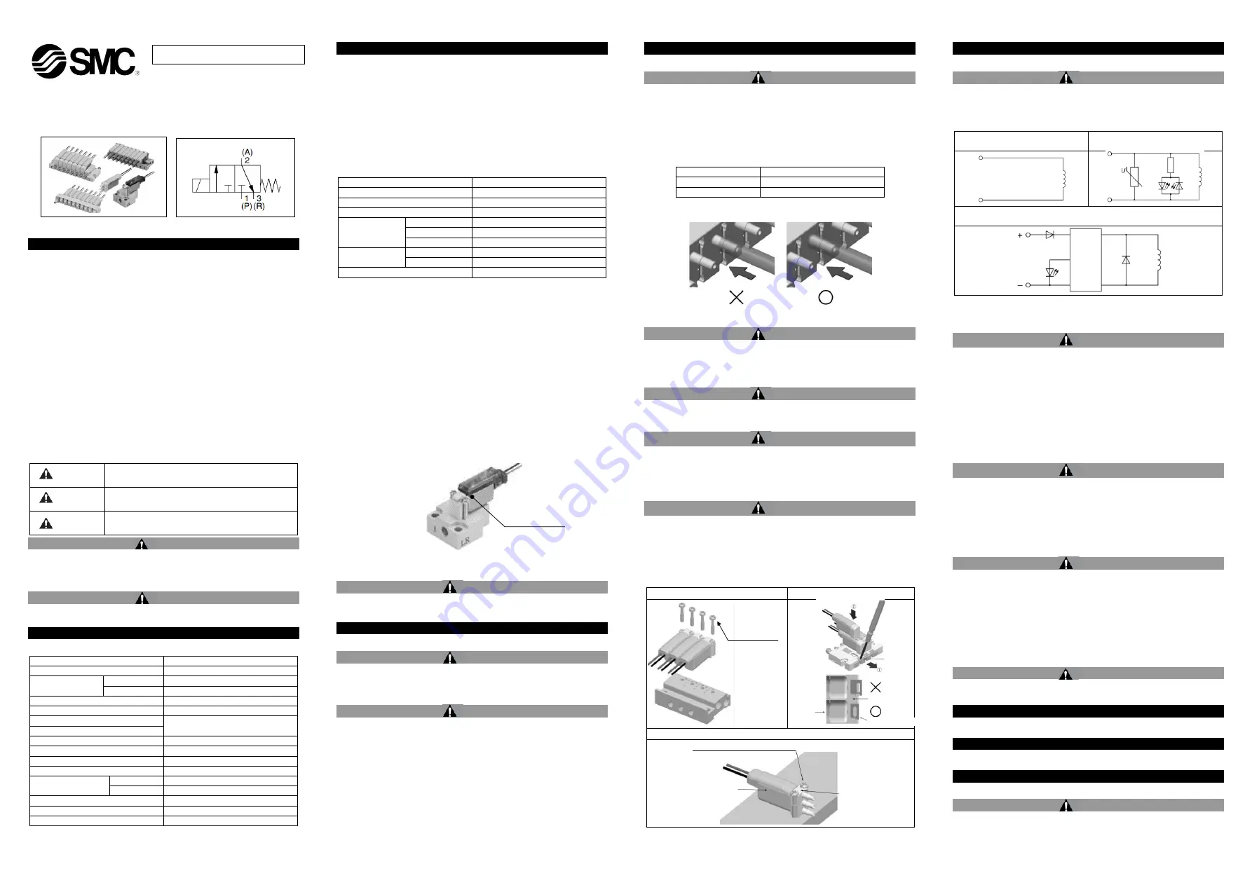
3 Port Solenoid Valve
Series S070
The intended use of this valve is to control the movement of an actuator.
1 Safety Instructions
These safety instructions are intended to prevent hazardous situations
and/or equipment damage. These instructions indicate the level of
potential hazard with the labels of “Caution,” “Warning” or “Danger.”
They are all important notes for safety and must be followed in addition
to International Standards (ISO/IEC)
*1)
, and other safety regulations.
*1)
ISO 4414: Pneumatic fluid power - General rules relating to systems.
ISO 4413: Hydraulic fluid power - General rules relating to systems.
IEC 60204-1: Safety of machinery - Electrical equipment of machines.
(Part 1: General requirements)
ISO 10218-1: Robots and robotic devices - Safety requirements for
industrial robots - Part 1: Robots.
•
Refer to product catalogue, Operation Manual and Handling
Precautions for SMC Products for additional information.
•
Keep this manual in a safe place for future reference.
Caution
Caution indicates a hazard with a low level of risk which, if
not avoided, could result in minor or moderate injury.
Warning
Warning indicates a hazard with a medium level of risk
which, if not avoided, could result in death or serious injury.
Danger
Danger indicates a hazard with a high level of risk which, if
not avoided, will result in death or serious injury.
Warning
•
Always ensure compliance with relevant safety laws and
standards.
•
All work must be carried out in a safe manner by a qualified person in
compliance with applicable national regulations.
Caution
•
The product is provided for use in manufacturing industries only. Do
not use in residential premises.
2 Specifications
2.1 Valve specifications
Valve construction
Poppet
Fluid
Air / Low vacuum (1.33 x 10
2
Pa)
Maximum operating
pressure [MPa]
Note 1)
0.35 W / 0.1 W
0.3
0.5 W
0.5
Proof pressure [MPa]
1
Ambient
and fluid temperature [˚C]
Note 2)
-10 to 50 (no freezing)
Flow rate characteristics
Refer to catalogue
Response time
Duty cycle
Contact SMC
Minimum operating frequency [Hz]
1 cycle / 30 days
Manual override
None
Lubrication
Not required
Impact/Vibration
resistance [m/s
2
]
Note 3)
0.35 W / 0.5 W
150 / 30
0.1 W
50 / 10
Enclosure (based on IEC60529)
IP40
Mounting orientation
Unrestricted
Weight [g] (valve only)
5
Table 1.
2 Specifications - continued
Note 1) With the low vacuum specification, the operating pressure range is 1.33 x
10
2
Pa to the maximum operating pressure.
Note 2) Use dry air to prevent condensation when operating at low temperatures.
Note 3) Impact resistance: No malfunction resulted in an impact test using a drop
impact tester. The test was performed one time each in the axial and right
angle directions of the main valve and armature, for both energized and de-
energized states. (Values quoted are for a new valve).
Vibration resistance: No malfunction resulted in 45 to 2000 Hz, a one-
sweep test performed in the axial and right angle directions of the main
valve and armature for both energized and de-energized states. (Values
quoted are for a new valve).
2.2 Solenoid specifications
Electrical entry
Grommet (G), Plug lead (C)
Coil rated voltage [VDC]
24, 12, 6, 5, 3
Allowable voltage fluctuation
Note 1)
±10% of rated voltage
Coil insulation class
Class B or equivalent
Power
consumption [W]
Note 2)
Standard
0.35
High voltage
0.5
Holding
Note 3)
0.1
Surge voltage
suppressor
0.35 W / 0.5 W
Varistor
0.1 W
Diode
Indicator light
LED
Table 2.
Note 1) Care should be taken about the voltage drop when the rated voltage is 6
VDC or less or when the response speed is important.
Note 2) With a light/surge voltage suppressor and power saving circuit, the light
consumes a power equivalent to 2 mA.
Note 3) 0.1 W specification is only available with 24 VDC plug lead type.
2.3 Manifold specifications
Refer to catalogue.
2.4 Indicator light
Figure 1. Only for Plug lead (C) type
2.5 Special products
Warning
Special products (-X) might have specifications different from those
shown in this section. Contact SMC for specific drawings.
3 Installation
3.1 Installation
Warning
•
Do not install the product unless the safety instructions have been read
and understood.
3.2 Environment
Warning
•
Do not use in an environment where corrosive gases, chemicals, salt
water or steam are present.
•
Do not use in an explosive atmosphere.
•
Do not expose to direct sunlight. Use a suitable protective cover.
•
Do not install in a location subject to vibration or impact in excess of
the product’s specifications.
•
Do not mount in a location exposed to radiant heat that would result in
temperatures in exce
ss of the product’s specifications.
3 Installation - continued
3.3 Piping
Caution
•
Before connecting piping make sure to clean up chips, cutting oil, dust
etc.
•
When installing piping or fittings, ensure sealant material does not
enter inside the port. When using seal tape, leave 1 thread
exposed
on the end of the pipe/fitting.
•
Tighten M3 screws 1/4 turn past hand tightness, and M5 screws by 1/6
turn past hand tightness (1/4 turn for miniature fittings) and to the
specified tightening torque as per below table.
Connection threads
Proper tightening torque [N
∙m]
M3
0.4 to 0.5
M5
1 to 1.5
Table 3.
3.3.1 Tubing installation
Figure 2.
3.4 Lubrication
Caution
•
SMC products have been lubricated for life at manufacture, and do not
require lubrication in service.
•
If a lubricant is used in the system, refer to catalogue for details.
3.5 Air supply
Warning
•
Use clean air. If the compressed air supply includes chemicals,
synthetic materials (including organic solvents), salinity, corrosive gas
etc., it can lead to damage or malfunction.
Caution
•
Install an air filter upstream of the valve. Select an air filter with a
filtration size of 5
μm or smaller.
3.6 Mounting
Caution
•
Ensure gaskets are in good condition, not deformed and are dust and
debris free.
•
When mounting valves ensure gaskets are present, aligned and
securely in place. After tightening by hand, tighten an additional 1/4
rotation for M3 and 1/6 rotation for M5. Tighten the screws to torque
levels as per figure below.
•
Refer to catalogue for additional information.
Base mounted with screws
Base mounted with clips
Solenoid valve fixing procedure (body ported single unit)
Figure 3.
3 Installation - continued
3.7 Electrical circuits
Caution
Surge suppression should be specified by using the appropriate part
number. If a valve type without suppression (Type ‘G’) is used,
suppression must be provided by the host controller as close as possible
to the valve.
Grommet
Plug lead
(With light/surge voltage suppressor)
With power saving circuit
(Energizing time before holding power kicks in: 100 ms)
Table 4.
Note)
There is no polarity for Grommet type or Plug lead type.
3.8 Residual voltage of the surge voltage suppressor
Caution
•
The suppressor arrests the back EMF voltage from the coil to a level
in proportion to the rated voltage.
•
Ensure the transient voltage is within the specification of the host
controller.
•
Contact SMC for the varistor residual voltage.
•
In the case of a diode, the residual voltage is approximately 1 V.
•
Valve response time is dependent on surge suppression method
selected.
3.9 Countermeasure for surge voltage
Caution
•
At times of sudden interruption of the power supply, the energy stored
in a large inductive device may cause non-polar type valves in a de-
energized state to switch.
•
When installing a breaker circuit to isolate the power, consider a valve
with polarity (with polarity protection diode), or install a surge
absorption diode across the output of the breaker.
3.10 Extended periods of continuous energization
Warning
If a valve will be continuously energized for an extended period of time,
the temperature of the valve will increase due to the heat generated by
the coil assembly. This will likely adversely affect the performance of the
valve and any nearby peripheral equipment. Therefore, if the valve is to
be energized for periods of longer than 30 minutes at a time or if during
the hours of operation the energized period per day is longer than the de-
energized period, we advise using valves with power saving circuit (type
E or F).
3.11 Effect of back pressure when using a manifold
Warning
Use caution when valves are used on a manifold because an actuator
may malfunction due to back-pressure.
4 How to Order
Refer to catalogue
for ‘How to Order’.
5 Outline Dimensions
Refer to
catalogue
for outline dimensions.
6 Maintenance
6.1 General maintenance
Caution
•
Not following proper maintenance procedures could cause the product
to malfunction and lead to equipment damage.
•
If handled improperly, compressed air can be dangerous.
ORIGINAL INSTRUCTIONS
Indicator light
Mounting
bracket
Manifold base
Manifold bracket
Mounting screws
Tightening torque:
0.1 N∙m to 0.14 N∙m
Solenoid
valve body
Solenoid cover (Metal)
Body (Resin)
Mounting screws (secures the body)
Tightening torque: 0.05
N∙m to 0.
07
N∙m
S
OL
.
S
OL
.
S
OL
.
Di
o
d
e
V
a
rist
o
r
.
LED
Power
saving
circuit


