


Front matter 3
Series
MY3
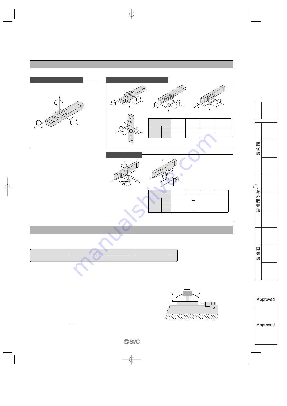
Types of Moment Applied to Rodless Cylinders
Multiple moments may be generated depending on the mounting orientation, load and position of the center of gravity.
Calculation of Guide Load Factor
1. Maximum load weight (1), static moment (2), and dynamic moment (3) (at the time of impact with stopper) must be examined for the selection calculations.
∗
To evaluate, use
υ
a (average speed) for (1) and (2), and
υ
(impact speed
υ
= 1.4
υ
a) for (3). Calculate m max for (2) from the maximum allowable load graph (m
1
, m
2
, m
3
)
and Mmax for (2) and (3) from the maximum allowable moment graph (M
1
, M
2
, M
3
).
2. Reference formulas [Dynamic moment at impact]
Use the following formulas to calculate dynamic moment when taking stopper impact into consideration.
m : Load weight (kg)
F
: Load (N)
F
E
: Load equivalent to impact (at impact with stopper) (N)
υ
a : Average speed (mm/s)
M : Static moment (N
•
m)
υ
= 1.4
υ
a (mm/s) F
E
= 1.4
υ
a x
δ
x m
•
g
1
M
E
= —
•
F
E
•
L
1
= 4.57
υ
a
δ
m L
1
(N
•
m)
3
Note 4) 1.4
υ
a
δ
is a dimension less coefficient for calculating impact force.
Note 5) Average load coefficient = :
This coefficient is for averaging the maximum load moment at the time of stopper impact according to service life calculations.
3. For detailed selection procedure, please refer to pages 2, 3, 18, 19.
Coordinates and Moments
z
y
M
3
: Yawing
x
M
2
: Rolling
M
1
: Pitching
Horizontal
mounting
Wall
mounting
Ceiling
mounting
m
3
x
g
x
M
2
z
M
3
X
Z
y
m
1
x
g
M
1
X
x
M
2
Y
y
m
2
x
g
M
1
X
x
M
2
Y
Vertical
mounting
g
: Gravitational acceleration
M
1
Z
M
3
z
y
Y
Note)
m
4
is a mass movable by thrust. Use 0.3 to 0.7 times the thrust
(differs depending on the operating speed) as a guide for actual use.
Mounting direction
Static load m
Horizontal
m
1
Ceiling
m
2
Wall
m
3
M
1
M
2
M
3
m
1
x
g
x X
m
1
x
g
x Y
—
m
2
x
g
x X
m
2
x
g
x Y
—
—
m
3
x
g
x Z
m
3
x
g
x X
m
4
x
g
x Z
—
m
4
x
g
x Y
Vertical
m
4
M
1
F
E
M
3
Y
υ
a
Mounting direction
Dynamic load F
E
Horizontal
Ceiling
Wall
Vertical
Note) Regardless of the mounting orientation, dynamic moment is
calculated with the formulae above.
Dynamic moment M
2E
will not be generated.
1.4
υ
a
x
δ
x
m
n
x
g
x F
E
x Z
1
3
x F
E
x Y
1
3
M
1E
M
2E
M
3E
Load Weight and Static Moment
g
: Gravitational acceleration
υ
a
: Average speed
δ
: Bumper coefficient
Note 1) Moment caused by the load, etc., with cylinder in resting condition.
Note 2) Moment caused by the impact load equivalent at the stroke end (at the time of impact with stopper).
Note 3) Depending on the shape of the work piece, multiple moments may occur. When this happens, the sum of the load factors (
Σα
) is the total of all such moments.
F
E
M
E
m
L
1
υ
Z
F
E
M
1E
υ
a
M
3E
Dynamic Moment
m
n
x
g
m
n
x
g
m
4
x
g
Static
moment
Dynamic
moment
Note)
Σ
α
=
+
+
< 1
=
Load weight
[
m
]
Maximum load weight
[
m max
]
Static moment
[
M
]
Allowable static moment
[
Mmax
]
Sum of guide
load factors
Note 1)
Dynamic moment [M
E
]
Allowable dynamic moment
[
M
E
max
]
Note 2)
Note 5)
Note 4)
1
3
•
•
•
υ
: Impact speed (mm/s)
L
1
: Distance to the load’s center of gravity (m)
M
E
: Dynamic moment (N
•
m)
δ
: Bumper coefficient
With rubber bumper = 4/100
With air cushion = 1/100
With shock absorber = 1/100
g : Gravitational acceleration (9.8 m/s
2
)
( )
MY3A3B.qxd 06.2.17 9:13 AM Page 6


