-47-
No. JXC
※
-OMY0008
12. Operation Examples
12.1 Positioning Operation
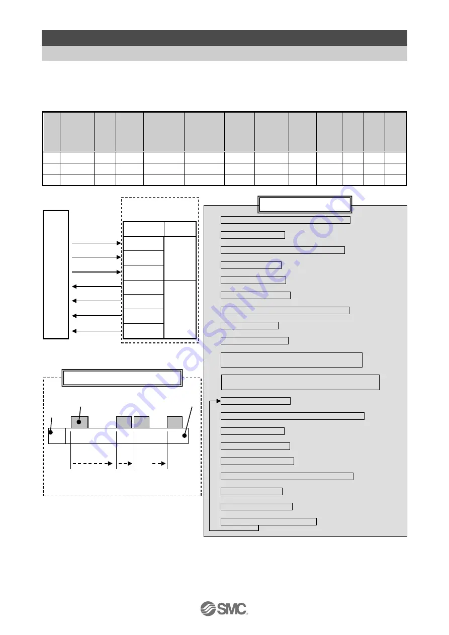
E.g.) Move an actuator from the origin to 100mm point at 50mm/s. (Step No.1 instruction)
Next, move the actuator from the 50mm point to 100mm point by moving it 5 times continuously,
10mm at a time, at a speed of 50mm/s. (Step No. 2)
■[Normal mode] Step data
(e.g.)
No.
Movement
mode
Speed
mm/s
Position
(mm)
Acceleration
mm/s
2
Deceleration
mm/s
2
Pushing
force
%
Threshold
Force
Value
%
Pushing
speed
Speed
mm/s
Moving
force
%
Area 1
(mm)
Area 2
(mm)
In pos
(mm)
0
-
-
-
-
-
-
-
-
-
-
-
-
1
Absolute
100
50.00
1000
1000
0
0
0
100
0
0
0, 1
2
Relative
50
10.00
1000
1000
0
0
0
100
0
0
0, 1
(1) Select/input Step No.1. (Turn ON "IN0")
↓
(2) Turn ON "DRIVE"
↓
Start moving to the position of Step No.1.
↓
(3) ”INP” turns OFF.
↓
(4) "BUSY" turns ON.
↓
∗
1
(5) Turn OFF "DRIVE".
↓
(6) Step No.1 is output. ("OUT1" turns ON)
↓
(7) “INP” turns ON.
↓
(8) "BUSY" turns OFF.
↓
The move to the position set in Step Data No.1
is completed.
↓
(9) Select/input Step No.2.
(Turn OFF "IN0" OFF and turn ON "IN1".
↓
(10) Turn ON "DRIVE".
↓
Start moving to 10mm from the current position.
↓
(11) “INP” turns OFF.
↓
(12) "BUSY" turns ON.
↓
*1
(13) Turn OFF "DRIVE".
↓
(14) Step No.2 is output. ("OUT1" turns ON)
↓
(15) “INP” turns ON.
↓
(16) "BUSY" turns OFF.
↓
The 10 mm move is completed.
Actuator
0mm
Origin position
M
Motor
Load
---
100mm
End position
50mm 60mm
・・・
PL
C
(2), (5), (10), (13)
(14), (11), (6), (3)
(16), (12), (8), (4)
(15)
(7)
(9)
(1)
Controller
Signal name Category
DRIVE
Control
signals
IN0
IN1
OUT0
Status
signals
OUT1
INP
BUSY
5 times
∗
1 “SVRE” and ”SETON” must be ON.
(E.g.) Operation
(E.g.) Flow chart


