background image


3. Start Menu 
 

An ACT Controller Menu icon is displayed on the desktop after installing the software. Double click 
the icon to display the menu shown below. Click the "Normal Mode" or "Easy Mode". 


4. Communication Setting 
 

When activating the "Normal mode" or "Easy mode", the software recognizes the connected controller 

automatically. 

However,  if  the  communication  settings  such  as  COM  port  number  are  incorrect,  communication 

cannot be established. 

Therefore, the communication setting is required. 


Confirm the following points before starting the communication. 

That power is supplied to the connected controller. 
The controller and the computer are connected to each other via the communication unit. 


<Normal Mode> 

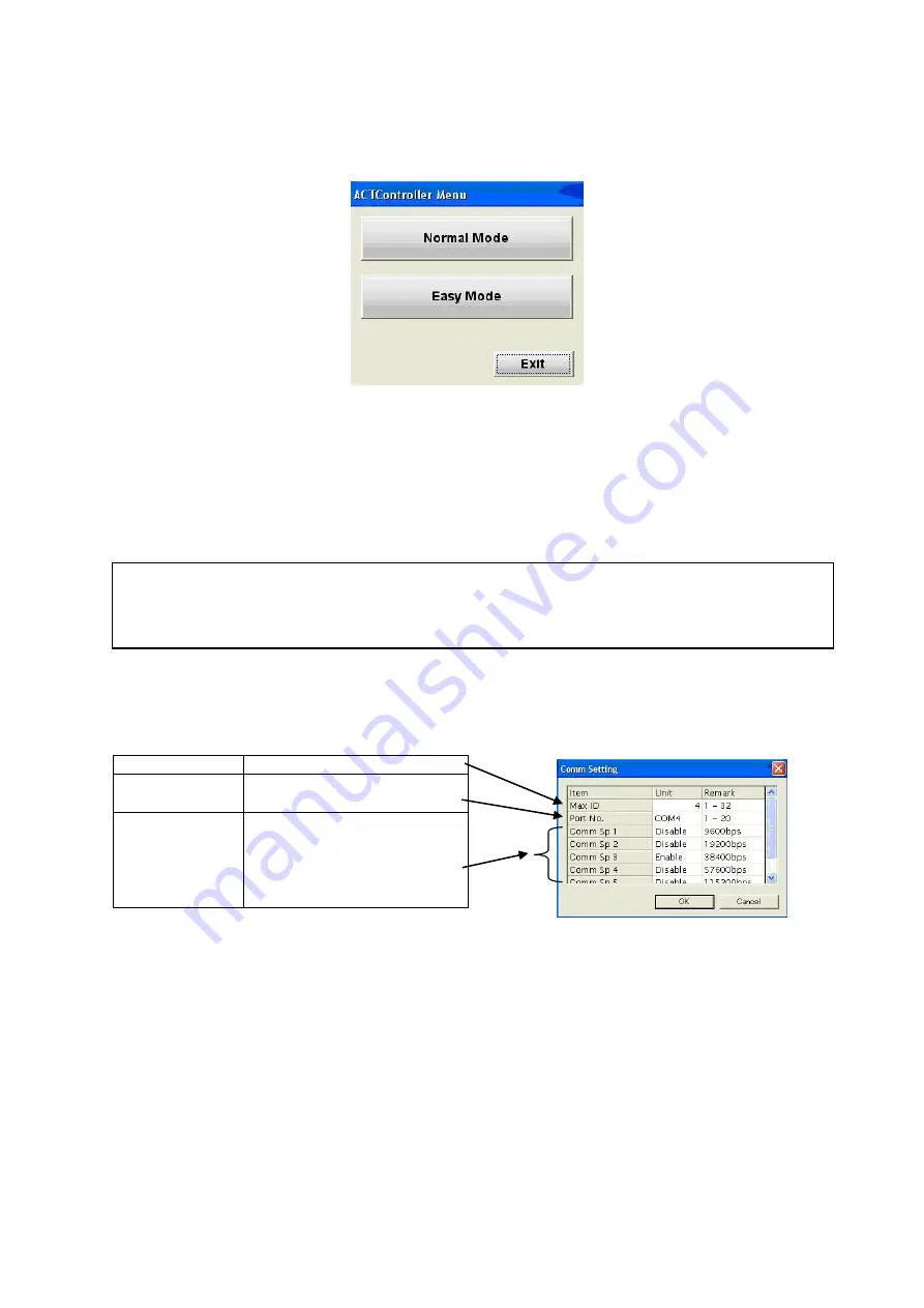
By  selecting  the  "Action"  ->  "System"  ->  "Setting"  in  the  menu  bar,  the  window  shown  below  is 

displayed. Set the COM port number as confirmed according to the instructions in "2. Check of the 
communication port".   


Selecting the "Action" -> "System" -> "Reset" after the setting, will initiate the software to recognize 

the connected controller.   

Maximum axis 

Sets the number of axis   

COM port 

Sets the COM port No. of the 
communication unit 

Communication 
speed 

Specifies the communication 
speed to the controller 
* The default communication 

speed  of  the  controller 
(LEC/JXC) is 38400 bps.   


Summary of Contents for JXC-W2

Page 1: ...Document No JXC OMU0012 Product Name Controller Setting Kit Installation Manual For Windows 8 1 Model Series LEC W2 JXC W2...

Page 2: ...load USB driver in advance and decompress it to a retrievable location such as the desktop on the PC 0 2 Preparation of USB Cable Prepare a communication cable LEC W2 C and an USB cable A miniB LEC W2...

Page 3: ...click the SMC Serial Converter and select the Update Driver Software The Update Driver Software may not be displayed when the automatic retrieval processing is executed Please try again after waiting...

Page 4: ...older where the USB driver was stored Check the Include subfolders Click the Next 6 The following confirmation screen is displayed Select the Install This screen may not be displayed if the SMC USB dr...

Page 5: ...r again Confirm that the SMC Serial Converter Part A in the lower figure was added to the Universal Serial Bus controllers Then right click the USB Serial Port Part B in the lower figure in the Other...

Page 6: ...he desktop when the installation is completed Click the icon to start the software Be sure to read 2 Check the Communication Port before starting the software 2 Check the Communication Port Before usi...

Page 7: ...rial Port in the Ports COM LPT In the case of the lower figure the COM No is 3 The COM No will change depending on the USB port where the communication cable is currently connected to Please check it...

Page 8: ...rting the communication That power is supplied to the connected controller The controller and the computer are connected to each other via the communication unit Normal Mode By selecting the Action Sy...

Page 9: ...n the connection is confirmed after the communication setting 5 Functions of Each Mode Refer to the ACT Controller ACT Control Help in the Program menu Start button on desktop screen for the functions...

Page 10: ...4 1 Sotokanda Chiyoda ku Tokyo 101 0021 JAPAN Tel 81 3 5207 8249 Fax 81 3 5298 5362 URL http www smcworld com Note Specifications are subject to change without prior notice and any obligation on the p...

Reviews: