SMC Networks HRS200 Series Information Download Page 7

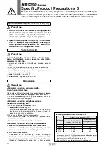
Protrusion when the conversion

fitting for circulating fluid

is mounted

Conversion fittings for circulating
fluid outlet, circulating fluid
return port, overflow port
Material: Stainless steel
3 pcs./set

Conversion fitting for automatic
fluid fill port
Material: Stainless steel
1 pc./set

Conversion fitting for tank drain
port
Material: Stainless steel
1 pc./set

Approx. 35 mm

Fig. 2 Caster adjuster-foot bracket (2 pcs.)

Fig. 3 Fixing bolt (8 pcs.)

Fig. 1 Mounting view

830

118

401

Fixing bolt (M8)

Unfixed caster
(Caster O.D.: ø75)

Adjuster foot

HRS200 

Series

Optional Accessories

w

 Caster Adjuster-foot Kit

This is a set of unfixed casters and adjuster feet stop.
When installed by user, it is necessary to lift the thermo-chiller by a forklift or sling work.
Carefully read the procedure manual included with this kit before performing the installation.

Part no.

Applicable model

HRS-KS002

HRS200-A

-46-

S

Parts List

Description

Procedure manual
Caster adjuster-foot bracket (2 pcs.)
Fixing bolt (M8) (8 pcs.)

HRS-EP013, HRS-EP014

q

 Piping Conversion Fitting

This is a fitting to change the port from Rc to G or NPT.
 · Circulating fluid outlet, Circulating fluid return port, Overflow port Rc1 

 NPT1 or G1

 · Drain port Rc3/4 

 NPT3/4 or G3/4

 · Automatic fluid fill port Rc1/2 

 NPT1/2 or G1/2

(It is not necessary to purchase this when pipe thread type F or N is selected in “How to Order” since it is included in the product.)

Part no.

Contents

Applicable model

HRS-EP013

NPT thread conversion fitting set

HRS200-A-46-

S

HRS-EP014

G thread conversion fitting set

6

Summary of Contents for HRS200 Series

Page 1: ...ort 1 This is a manual fluid fill port that is different from the automatic fluid fill port Fluid can be supplied manually into the tank without removing the side panel Fluid can be supplied manually...

Page 2: ...ay panel Eye bolt M12 4 places 715 556 851 1114 428 421 278 110 108 Overflow port Rc1 Automatic fluid fill port Rc1 2 Fluid level indicator Signal cable entry Hole 40 Grommet with membrane Power cable...

Page 3: ...Thermo chiller automatic fluid fill port 3 User s equipment To wastewater collection pit Fluid supply Circulating fluid return port Overflow port Tank drain port 4 5 2 2 2 2 1 1 6 Ensure that the ove...

Page 4: ...p when this function is operated o lamp Equipped with a power failure auto restart function which restarts the product automatically after stopped due to a power failure Lights up when this function i...

Page 5: ...optional accessories depending on the accessory the allowable current of 24 VDC devices will be reduced Refer to the operation manual of the optional accessories for details Item Specifications Conne...

Page 6: ...830 401 118 1538 HRS200 A 46 SW The circulating fluid temperature and pressure are displayed in SI units MPa C only If this option is not selected a product with a unit selection function will be prov...

Page 7: ...ed by user it is necessary to lift the thermo chiller by a forklift or sling work Carefully read the procedure manual included with this kit before performing the installation Part no Applicable model...

Page 8: ...ectric conductivity target 5 0 to 45 0 S cm Set range of electric conductivity hysteresis 2 0 to 10 0 S cm Operating temperature range Circulating fluid temperature 5 to 60 C Power consumption 400 mA...

Page 9: ...now Protection Hood Stainless steel snow protection hood for air cooled chiller According to the mounting direction of the snow protection hood the ventilation from the fan can be selected from four d...

Page 10: ...ment Element Parts List No Description Material Qty Note q Body PC PP 1 w Element 1 PP 1 e Extension piece Stainless steel 2 Conversion from NPT to Rc r Handle 1 When H is selected t Sealant tape PTFE...

Page 11: ...rm code 2 Operable items Operation start stop Circulating fluid temperature setting Alarm sound stop Key lock Key operation sound ON OFF Digital display brightness adjustment Alarm sound ON OFF HRS CV...

Page 12: ...0 C Circulating fluid return temperature T2 297 K 24 C Circulating fluid temperature difference iT 4 K T2 T1 Conversion factor minutes to seconds SI units 60 s min 1 Refer to the next page for the typ...

Page 13: ...1 kg L or using current unit system weight volume ratio 1 kgf L Specific heat C 4 19 x 103 J kg K or using current unit system 1 x 10³ cal kgf C 2 Values for density and specific heat change slightly...

Page 14: ...ulating fluid spec ified in Operation at low am bient temperature or low cir culating fluid temperature 5 In locations where condensation may occur 6 In locations which receive direct sunlight or radi...

Page 15: ...glycol aqueous solution 15 wt 5 to 10 Ethylene glycol aqueous solution 15 wt Be sure to read this before handling the products For safety instructions and tempera ture control equipment precautions re...

Page 16: ...nd tempera ture control equipment precautions refer to the Handling Precautions for SMC Prod ucts and the Operation Manual on the SMC website https www smcworld com HRS200 Series Specific Product Prec...

Page 17: ...mS cm 100 1 to 300 1 v v Chloride ion Cl mg L 50 or less v Sulfuric acid ion SO4 2 mg L 50 or less v Acid consumption amount at pH4 8 mg L 50 or less v Total hardness mg L 70 or less v Calcium hardnes...

Page 18: ...rformed or will stop Power supply voltage is not within the rated voltage range of 10 In case the water level inside the tank is reduced abnormally Circulating fluid temperature is too high Compared t...

Page 19: ...Safety Instructions Be sure to read the Handling Precautions for SMC Products M E03 3 and Operation Manual before use...

Reviews: