background image


17 

6  SYNC button Usage 

This section describes how to add or remove devices from a Powerline network by using the SYNC button on the 

devices. This process allows to create a Powerline network without using the configuration utility for Windows and 

works independent from the operating system. 

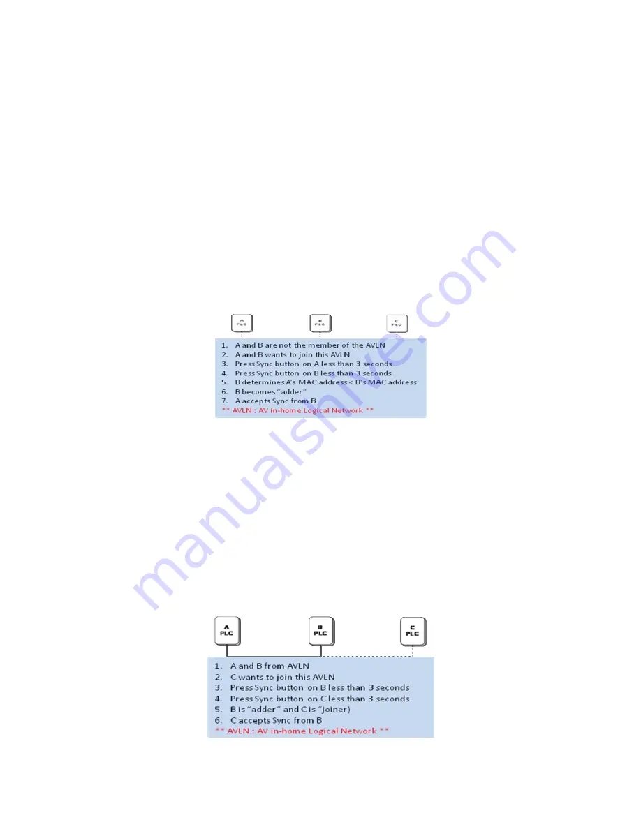
6.1  Creating a private network 

When two devices with different SYNC values are connected to the same Powerline private network, they need to be 

synchronized to be able to communicate: 

1. 

Press the SYNC button on device A for less than 3 seconds. 

2. 

Press the SYNC button on device B for less than 3 seconds. The button on device B must be pressed 

within 1 minute. 

3. 

Wait for the SYNC process to complete. 

The Power LED on both devices will blink evenly at 1-second intervals until the operation succeeded or failed. If the 

connection succeeded, it illuminates steadily. If an error occured, the Power LED on the ‘adder’ (Device B) blinks 

unevenly until the SYNC button on the ‘adder’ (Device B) is pressed again or the ‘joiner’ (Device A) is reset by 

pressing the SYNC button down for more than 10 seconds. 


Figure 6-1: Creating a Homeplug AV private network 

6.2  Joining a Network 

In this scenario a Powerline private network exists and a new device, the ‘joiner’, should join the network. Any device 

on the existing Powerline network can become the ‘adder’. 

1. 

Press the SYNC button on the ‘joiner’ (new device) for at least 3 seconds. 

2. 

Press the SYNC button on any network device for less than 3 seconds, making it the ‘adder’ (existing 

device). Please press this SYNC button within 1 minute. 

3. 

Wait for the connection to complete. 

The Power LED on both devices will blink evenly at 1-second intervals until the operation succeeded or failed. If the 

connection succeeded, it illuminates steadily. If an error occurred, the Power LED on the ‘adder’ blinks unevenly until 

the SYNC button on the ‘adder’ is pressed again or the ‘joiner’ is reset by pressing the RESET button down for more 

than 10 seconds. 


Figure 6-2: Joining a network 

Summary of Contents for EZ Connect Powerline SMCHPAV-ESW

Page 1: ......

Page 2: ...parties which may result from its use No license is granted by implication or otherwise under any patent or patent rights of SMC SMC reserves the right to change specifications at any time without no...

Page 3: ...Trademarks SMC is a registered trademark and EZ Connect Powerline is a trademark of SMC Networks Inc Other product and company names are trademarks or registered trademarks of their respective holder...

Page 4: ...and Product Registration To register SMC products and to review the detailed warranty statement please check www smc com for the warranty terms in your country region SMC Networks Inc 20 Mason Irvine...

Page 5: ...Essential Requirements of the EMC Directive 2004 108 EC and the LVD Directive 2006 95 EC of the European Union This equipment meets the following conformance standards EN 60950 1 2006 EN 61000 3 2 20...

Page 6: ...ACE 8 3 2 THE ADAPTER S BUTTONS 8 3 3 THE ADAPTER S LEDS 8 4 HOW TO INSTALLATION UTILITY 9 5 HOW TO USE THE UTILITY SOFTWARE 11 5 1 MAIN TAB 11 5 2 PRIVACY TAB 14 5 3 DIAGNOSTICS TAB 15 5 4 ABOUT TAB...

Page 7: ...drilling are required 1 1 System Requirements For Configuration Utility computer with Operating System Microsoft Windows 7 Vista 32 bits 64 bits XP or 2000 CPU Intel Pentium III or better clock rate f...

Page 8: ...vice and the AC power source Only a qualified technician should service this product Opening or removing covers may result in exposure to dangerous voltage points or other risks Do not plug the device...

Page 9: ...lding the NMK button for 0 5 to 3 seconds makes the adapter a member of the existing Powerline network Note For more information about the security button please see chapter 6 3 3 The Adapter s LEDs A...

Page 10: ...talled please uninstall it and restart your computer z Insert the Utility CD ROM into the computer s CD ROM drive Select SMCHPAV ETH2 Utility Installation and double click Setup exe Follow the on scre...

Page 11: ...10 Figure 4 3 Installation Complete Figure 4 4 Installation complete Click Close to complete installation...

Page 12: ...found on top of the Remote device panel The Network type Public or Private is also displayed based on the network status of the local device The scan status option is displayed on the top right corne...

Page 13: ...e of the device or the packaging and click OK to verify the password The password field accepts the device password in any format with or without dashes A confirmation box appears if the password was...

Page 14: ...ssword and add the device to the network If the device is not located a warning message appears Scan This button is used to perform an immediate search of the HomePlug devices connected to the Powerli...

Page 15: ...etwork name of the local device only If a new private network name other than HomePlugAV is entered all the devices that appeared in the lower panel of the Main screen will disappear effectively isola...

Page 16: ...f all devices that appeared on the computer over a certain period of time All the devices and the parameters of the devices on the powerline network are listed Devices that are active on the current l...

Page 17: ...n and provides an HTML link to a website such as www smc com Clicking the web address will open the website in your web browser Figure 5 6 About Dialog Tab Preferences The lower part of the panel may...

Page 18: ...on the adder Device B blinks unevenly until the SYNC button on the adder Device B is pressed again or the joiner Device A is reset by pressing the SYNC button down for more than 10 seconds Figure 6 1...

Page 19: ...SYNC button on the leaver for at least 10 seconds The device resets and restarts with a random SYNC 2 Wait for the reset to complete The Power LED on the leaver momentarily extinguishes during reset b...

Page 20: ...mprove the Transmission Capacity For the SMCHPAV ESW it is recommended to plug the device directly into a wall socket not into a power stripe This can significantly improve the transmission capacity o...

Page 21: ...AES LED s Power Ethernet 1 3 Ethernet Link and Activity Data PLC Link and Activity Push Button Reset Restore the default factory parameter Security Set up network password automatically Consumption 7...

Page 22: ...SMA CA Carrier Sense Multiple Access Collision Avoidance DAK Device Access Key DM Device Manager IGMP Internet Group Management Protocol NEK Network Encryption Key NID Network ID Identification SYNC S...

Page 23: ...t the channel access priority for IGMP frames these are the group management frames not the stream data Unicast default CAP 1 set the default channel access priority for unicast frames not matching an...

Page 24: ......

Reviews: