

EX600-SMY122EN
Page 1 of 2
Instruction Manual
Fieldbus device - SI unit for PROFINET
IO-Link compatible
EX600-SPN3 / SPN4
The intended use of this product is to control pneumatic valves and I/O
while connected to the PROFINET (and IO-Link) protocols.
1 Safety Instructions
These safety instructions are intended to prevent hazardous situations
and/or equipment damage. These instructions indicate the level of
potential hazard with the labels of “Caution,” “Warning” or “Danger.”
They are all important notes for safety and must be followed in addition
to International Standards (ISO/IEC)
*1)
, and other safety regulations.
*1)
ISO 4414: Pneumatic fluid power - General rules relating to systems.
ISO 4413: Hydraulic fluid power - General rules relating to systems.
IEC 60204-1: Safety of machinery - Electrical equipment of machines.
(Part 1: General requirements)
ISO 10218-1: Manipulating industrial robots -Safety. etc.
•
Refer to product catalogue, Operation Manual and
•
Handling Precautions for SMC Products for additional information.
•
Keep this manual in a safe place for future reference.
Caution
Caution indicates a hazard with a low level of risk which, if
not avoided, could result in minor or moderate injury.
Warning
Warning indicates a hazard with a medium level of risk
which, if not avoided, could result in death or serious injury.
Danger
Danger indicates a hazard with a high level of risk which, if
not avoided, will result in death or serious injury.
Warning
•
Always ensure compliance with relevant safety laws and
standards.
•
All work must be carried out in a safe manner by a qualified person in
compliance with applicable national regulations.
2 Specifications
The EX600 range of units can be connected to a fieldbus to realize the
reduction of input / output device wiring and a distributed control system.
The system communicates with the fieldbus through the SI unit.
One SI unit can be connected to manifold valves with up to 32 outputs,
and to input, output, I/O and IO-Link master units to a maximum of 9 units.
2.1 General specifications
Item
Specifications
Ambient temperature
-10 to +50
o
C
Ambient humidity
35 to 85% RH (no condensate)
Ambient storage temperature
-20 to +60
o
C
Withstand voltage
500 VAC applied for 1 minute
Insulation resistance
500 VDC, 10 M
Ω
or more
Enclosure rating
IP67 (manifold assembled)
Standard
EMC / RoHS directive, UL (CSA)
Weight
300 g
2 Specifications (continued)
2.2 Electrical specifications
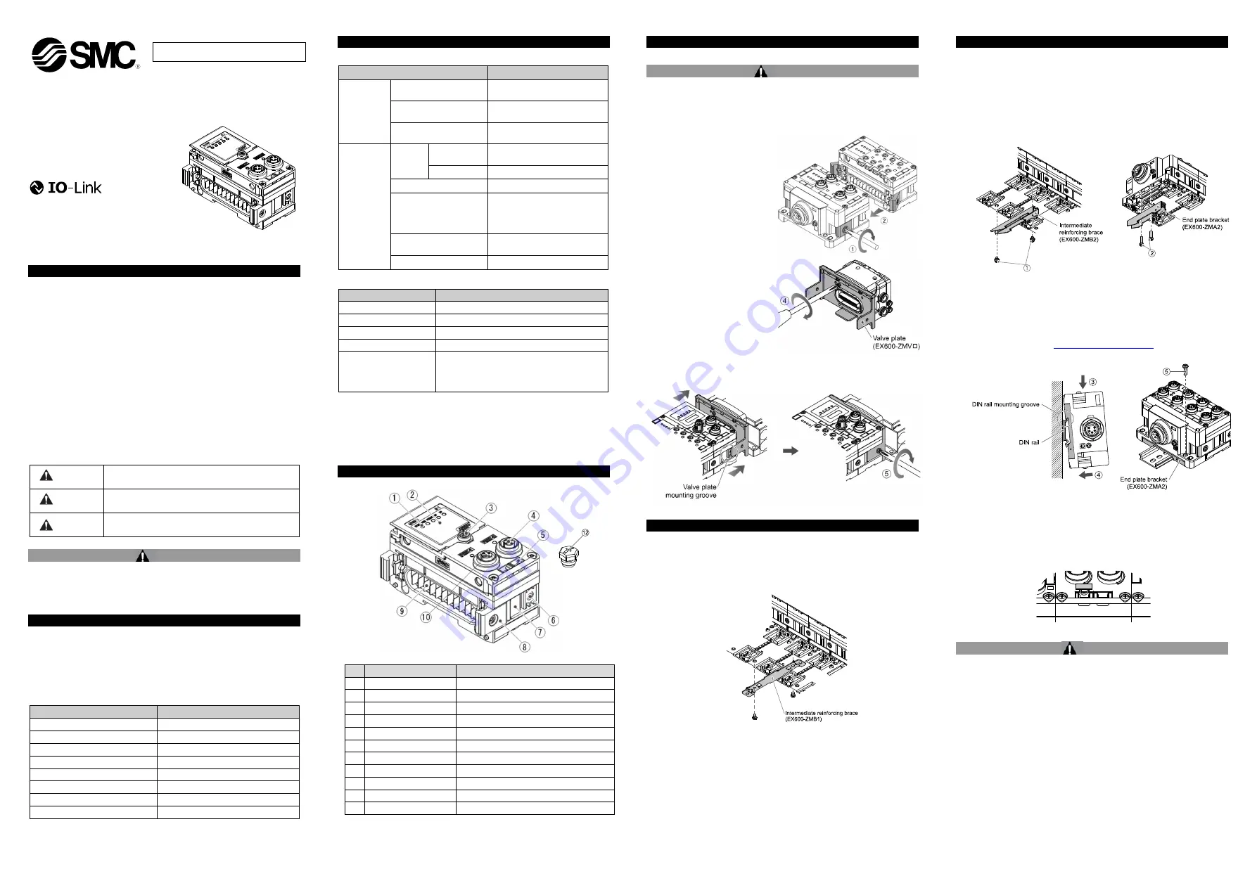
3 Name and function of Individual parts
No
Part
Description
1 LED display
Displays the SI unit status.
2 Display cover
Display cover for switch setting.
3 Display cover screw
To open the display cover.
4 Connector (PORT 2)
Connector for Fieldbus Outputs.
5 Marker groove
Groove for identification marker.
6 Valve plate hole
Hole for valve plate mounting.
7 Valve plate groove
Groove for valve plate mounting.
8 Joint bracket
Bracket for joining to adjacent units.
9 Unit connector
Connector for signal/power to next unit.
10 Connector (PORT 1)
Connector for Fieldbus Inputs.
12 Seal cap (2 pcs.)
For all unused M12 connectors
4 Assembly
4.1 Assembling the unit
Warning
Do not install the product unless the safety instructions have been read
and understood.
(1) Connect an I/O unit to the end plate. Digital and analogue units can
be connected in any order. Joint bracket screw tightening torque: 1.5
to 1.6 Nm.
(2) Add more I/O units. Up to 9
I/O units can be connected
to one manifold.
(3) Connect the SI unit. After
connecting the required I/O
units, connect the SI unit.
The connection method is
as above.
(4) Mount the valve plate
(EX600-ZMV#) to the valve
manifold using the valve
screws (M3 x 8) supplied.
(Tightening torque: 0.6 to
0.7 Nm).
(5) Connect
the
SI
unit
assembly to the valve
manifold.
Insert the valve plate into
the valve plate mounting
groove.
Then fix using the valve plate mounting screws (M4 x 6) supplied
(Tightening torque: 0.7 to 0.8 Nm).
5 Installation
•
Direct mounting
(1) When assembling six or more units, the middle part of the assembly
must be fitted with an intermediate reinforcing brace (EX600-ZMB1)
before mounting using 2-M4x5 screws (Tightening torque: 0.7 to 0.8
Nm).
(2) Mount and tighten the end plate at one end of the unit and mount the
intermediate reinforcing brace if required using M4 screws
(Tightening torque: 0.7 to 0.8 Nm).
Fix the end plate at the valve side while referring to the operation
manual for the applicable valve series.
5 Installation (continued)
•
DIN rail mounting
(1) When assembling six or more units, the middle part of the complete
assembly must be fitted with an intermediate reinforcing brace for DIN
rail mounting (EX600-ZMB2), using 2-M4 x 6 screws.
(Tightening torque: 0.7 to 0.8 Nm).
(2) Mount the end plate bracket (EX600-ZMA2) to the end plate using 2-
M4 x 14 screws (Tightening torque: 0.7 to 0.8 Nm)
.
For the SY series, use end plate bracket (EX600-ZMA3).
(3) Hook the DIN rail mounting groove on to the DIN rail.
(4) Press the manifold using its side hooked to the DIN rail as a fulcrum
until the manifold is locked onto the DIL rail.
(5) Fix the manifold by tightening the DIN rail fixing screws (M4 x 20) on
the end plate bracket (Tightening torque: 0.7 to 0.8 Nm).
Refer to the Operation Manual for the applicable valve series on the
SMC website (URL:
https://www.smcworld.com
) for the mounting
method of the valve manifold.
5.1 Identification marker
The signal name of the input or output devices and unit address can
be written on the marker and can be installed on each unit.
Mount a marker (EX600-ZT1) into the marker groove as required.
•
5.2 Environment
Warning
•
Do not use in an environment where corrosive gases, chemicals, salt
water or steam are present.
•
Do not install in a location subject to vibration or impact in excess of
the product’s specifications.
•
Do not mount in a location exposed to radiant heat that would result in
temperatures in excess of the product’s specifications.
Item
Specifications
Power
supply
voltage /
current
Control and Input
power supply
24.0 VDC
2.0 A max.
Solenoid valve and
Output power supply
24.0 VDC
2.0 A max.
Internal current
consumption
120 mA maximum
Solenoid
valve
specification
Output
type
EX600-SPN3
PNP / source (negative
common)
EX600-SPN4 NPN / sink (positive common)
Number of outputs
32 outputs
Applicable valve series
24 VDC and 1.0 W max.
Solenoid valve with surge
voltage suppression
(manufactured by SMC)
Output condition during
communication error
HOLD / CLEAR / Force ON
Protection function
Short circuit protection
2.3 Communication specifications
Item
Specifications
Protocol
PROFINET V2.35
Conformance class
Class C (only for IRT switch function)
Communication speed
100 Mbps
Configuration file
GSDML-V2.35-SMC-EX600-***.xml
Applicable functions
Fast Start Up
MRP (Media Redundancy Protocol)
System redundancy s.2
Web Server
ORIGINAL INSTRUCTIONS


