


-28-
No.EX##-OMK0004-A
○
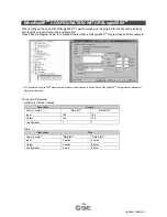
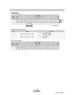
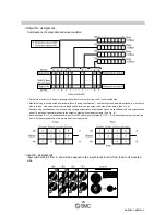
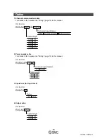
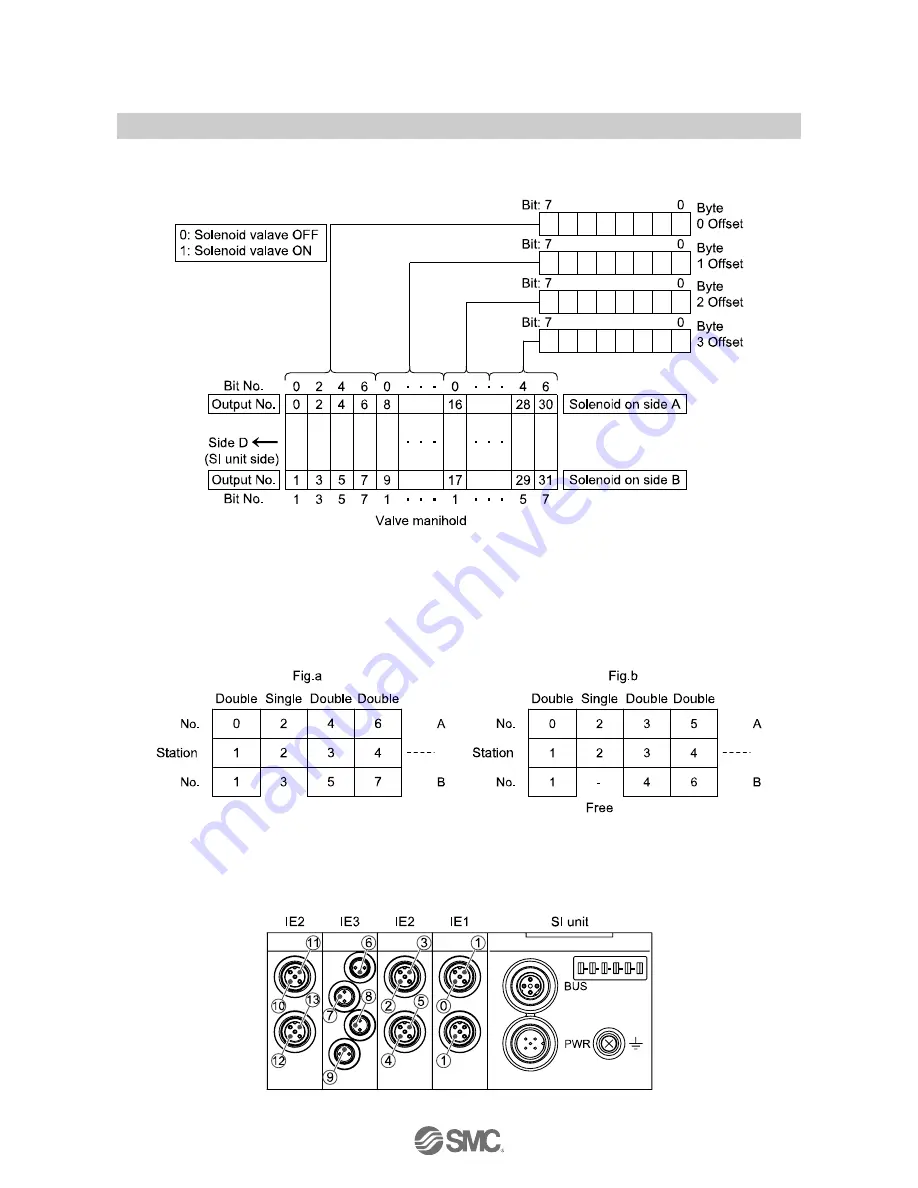
Output No. assignment
Combinations of output data and valve manifold
∗
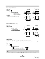
: Output No. starts from 0, and will be assigned to the valves in order from the SI unit mounted side.
∗
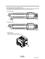
: Manifold wiring is double wired as standard ("double wiring specification"), and the output numbers are assigned in order from A
side to B side. If the mounted valves are single solenoid valves, the output on B side will be empty. (See Fig. a)
∗
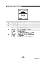
: Special wiring specification with a mixed wiring of single solenoid and double solenoid can be specified with a wiring specification
sheet. This makes it possible to specify the output numbers without empty outputs. (See Fig. b)
∗
: Each bit status, 0 or 1, of the data shows the ON or OFF solenoid valve status (0: OFF, 1: ON), and the output number starting
from 0 will be assigned to from the lowest bit of the memory data.
○
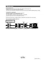
Input No. assignment
Input numbers start from 0, and will be assigned to the input blocks in order from the SI unit mounted
side.