background image


Version 6.00 
Date of editing: 16.09.2022

 r.


Page 18 of 30 

Technical documentation


KWP-L


7.2.


INSTALLATION TECHNOLOGY 

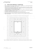
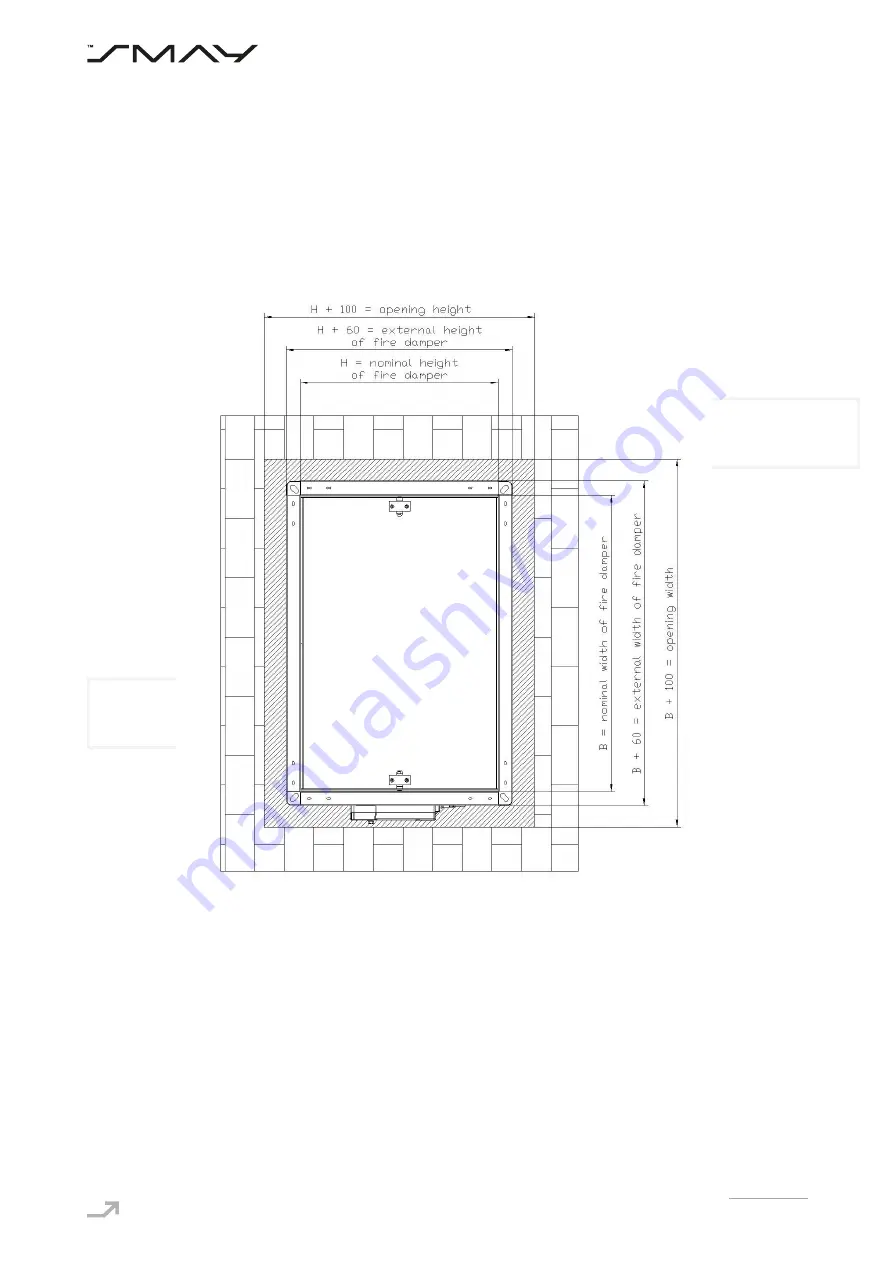
 RIGID WALL 

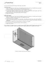
a.


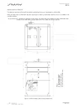
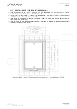
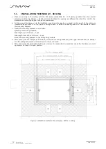
Make  an  opening  in  the  wall  with  the  dimensions  100  [mm]  (acceptable 

80  ÷  120  [mm]) 

greater  than  the 

nominal dimensions of the fire damper = B+100 and H+100. 

b.


Put the closed fire damper into the installation opening and support or suspend, in this way that the minimum 

installation depth mark is on the plane of wall surface. 

c.


After  setting  the  fire  damper  as  described,  fill  the  gap  between  the  fire  damper  and  the  wall  with  cement, 

cement-lime mortar or concrete. 

d.


After the mortar has dried (about 48 hours), remove the supports or suspensions, check the fire damper correct 

operation and leave it in open position. 


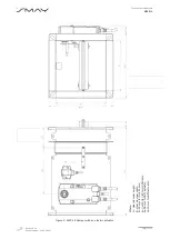
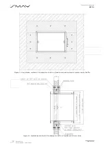
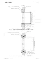
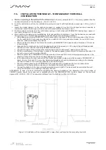
Figure 6. Installation method of fire dampers  KWP-L in rigid wall with vertical rotation axis of baffle


Summary of Contents for KWP-L

Page 1: ...a Technical Documentation KWP L Fire Damper rectangular v https www smay eu ...

Page 2: ...nsitivity Closing opening during the test at the right time Pass Response time Closure time Pass Reliability 50 cycles 120s Fire resistance Fire integrity E Fire insulation l Smoke leakage S Mechanical stability under E Maintenance of the cross section under E EI 120 ve ho i o S EI 90 ve i o S EI 60 ve i o S EI 30 ve i o S Durability Opening and closing cycle test 1 KWP LE 10 000 cycles 120s 1 KWP...

Page 3: ... DESCRIPTION 5 5 BELIMO ELECTRIC ACTUATORS USED IN KWP LE 8 6 CONDITIONS OF TRANSPORT AND STORAGE 15 7 INSTALLATION TECHNOLOGY 15 7 1 INSTALLATION TECHNOLOGY CEILING 16 7 2 INSTALLATION TECHNOLOGY RIGID WALL 18 7 3 INSTALLATION TECHNOLOGY FLEXIBLE WALL 20 7 4 INSTALLATION TECHNOLOGY CONSTRUCTIONS OF GREAT THICKNESS 23 7 5 INSTALLATION TECHNOLOGY MONTAGE AWAY FROM WALL CONSTRUCTION 24 8 PRINCIPLES ...

Page 4: ...e and a fire resistance class EI120 or higher rigid walls with low density 650 200 kg m3 or higher 100 mm in thickness or more and EI120 or a higher fire resistance class e g concrete walls solid brick walls cellular concrete block walls hollow masonry unit walls or concrete slab walls flexible walls 125 mm in thickness or more and EI 120 or a higher fire resistance class thicker higher density mo...

Page 5: ...er mounted directly in a floor i o operating effectiveness criteria are met from inside to outside fire inside and from outside to inside fire outside The KWP L fire dampers may also be installed in buildings partitions with a lower fire resistance rating In this case the damper fire resistance rating is equal to the partition fire resistance rating subject to the smoke leakage criterion The KWP L...

Page 6: ...position The movement of the baffle is limited by two buffers The KWP LE damper is provided with an electric spring return actuator BFL BFN or BF series manufactured by BELIMO and the BAT or BAE thermal fuse 72 C 95 C optionally constituting damper s drive system supplied by the 230 V AC or 24 V AC DC voltage After the voltage has been supplied the actuator rotates the baffle to the open position ...

Page 7: ...d with inspection openings for checking the damper condition once it is installed in the ventilation system In a special version resistant to aggressive environments all components of the damper are made of stainless steel whereas the damper baffle is impregnated with a fire resistant board impregnation Figure 1 KWP LS damper with a spring mechanism Where H clear damper height B clear damper width...

Page 8: ...2 r Page 7 of 30 Technical documentation KWP L Figure 2 KWP LE damper with an electric actuator Where H clear damper height B clear damper width C 25 mm for H 250 mm C H 10 2 80 for H 250 mm D 28 mm for BFL actuator D 30 mm for BFN actuator ...

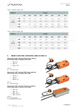
Page 9: ... 1 12 1 300 5 7 6 9 8 2 9 4 10 3 11 8 13 0 14 2 400 8 0 9 4 10 8 12 2 13 6 14 9 16 3 500 10 6 12 2 13 7 15 3 16 9 18 4 5 BELIMO ELECTRIC ACTUATORS USED IN KWP LE Spring return 90 actuator BFL series combined with thermoelectric tripping device BAT BFL230 T BFL24 T BFL24 T ST where ST connection plug Spring return 90 actuator BFN series combined with thermoelectric tripping device BAT BFN230 T BFN2...

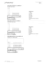
Page 10: ...Version 6 00 Date of editing 16 09 2022 r Page 9 of 30 Technical documentation KWP L Wiring diagram BFL230 T and BFN230 T Wiring diagram BFL24 T and BFN24 T Wiring diagram BFL24 T ST and BFN24 T ST ...

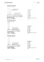
Page 11: ...Version 6 00 Date of editing 16 09 2022 r Page 10 of 30 Technical documentation KWP L Wiring diagram BFL24 SR T Wiring diagram BF230 TN Wiring diagram BF24 TN ...

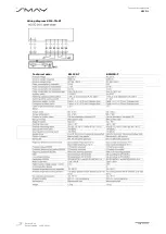
Page 12: ...Version 6 00 Date of editing 16 09 2022 r Page 11 of 30 Technical documentation KWP L Wiring diagram BF24 TN ST Technical data BFL230 T BFN230 T ...

Page 13: ...Version 6 00 Date of editing 16 09 2022 r Page 12 of 30 Technical documentation KWP L Technical data BFL24 T ST BFN24 T ST ...

Page 14: ...Version 6 00 Date of editing 16 09 2022 r Page 13 of 30 Technical documentation KWP L Technical data BF230 TN ...

Page 15: ...Version 6 00 Date of editing 16 09 2022 r Page 14 of 30 Technical documentation KWP L Technical data BF24 TN ...

Page 16: ...ed by the warranty To opening fire dampers KWP LS use a key mounted on damper casing Before installing secure the fire damper by dust and dirt using a foil or other screening material It can prevent components of fire damper by damage To be able to preserve the declared resistance insulation and smoke leakage EIS120 EIS90 EIS60 EIS30 dampers should be installed on wall which was classified as EIS1...

Page 17: ...h mark is on the plane of ceiling surface or inside the opening and that it is possible to install the mounting brackets c Install the mounting brackets on each side Quantity of mounting brackets Side length up to 500 mm 1 pcs Side length from 500 to 800 mm 2 pcs Mount the mounting brackets to the ceiling using dowels d After setting the fire damper as described mount the mounting brackets fill th...

Page 18: ...iling with thickness greater than 150 mm connect the damper to the duct before the damper isolation with cement mortar the damper frame will be bricked up along with a part of the duct Actuator under ceiling Actuator above ceiling E mm Thickness of ceiling 69 96 Figure 4 Proposed dimensions of mounting brackets for installation in a ceiling 140 mm thick ...

Page 19: ...stallation opening and support or suspend in this way that the minimum installation depth mark is on the plane of wall surface c After setting the fire damper as described fill the gap between the fire damper and the wall with cement cement lime mortar or concrete d After the mortar has dried about 48 hours remove the supports or suspensions check the fire damper correct operation and leave it in ...

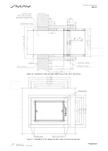
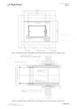
Page 20: ...g 16 09 2022 r Page 19 of 30 Technical documentation KWP L Figure 7 Installation method of fire dampers KWP L in rigid wall with horizontal rotation axis of baffle Figure 8 Installation method of fire dampers KWP L in rigid wall ...
Page 21: ...Put the closed fire damper into the installation opening and support or suspend in this way that the minimum installation depth mark is on the plane of the flange surface d After setting the fire damper as described fill the gap between the fire damper and the wall with non flammable mineral wool of high density 100 kg m3 or more e Seal the place of filling with mineral wool using the sealing comp...

Page 22: ...22 r Page 21 of 30 Technical documentation KWP L Figure 10 Installation method of fire dampers KWP L in flexible wall with horizontal rotation axis of baffle Figure 11 Installation method of fire dampers KWP L in flexible wall 75 mm thick ...
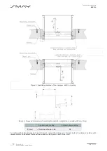
Page 23: ...ting 16 09 2022 r Page 22 of 30 Technical documentation KWP L Figure 12 Installation method of fire dampers KWP L in flexible wall 100 mm thick Figure 13 Installation method of fire dampers KWP L in flexible wall 125 mm thick ...

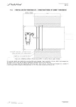
Page 24: ... of great thickness In rigid and flexible wall construction and in ceiling with thickness less or equal to 140 mm KWP L fire dampers are mounted in such a way that the damper baffle axis matches the axis of the structure Whereas in case of walls and ceilings with thickness higher than 140 mm the KWP L fire dampers are mounted in such a way that the damper building boundary i e 210 mm is maintained...

Page 25: ...uct along with the spacing strips in the spacing L 55 using rails and threaded rods Connect the duct with the wall using PROMAT K84 adhesive Connect the sides of the duct together using adhesive and 6 0x90 screws spacing about 200 mm On the circumference of the damper in place of the swelling gasket place strips of mineral wool density 100 kg m3 or more with a profile of 46x30 Make frontal bands o...

Page 26: ...te of editing 16 09 2022 r Page 25 of 30 Technical documentation KWP L Figure 16 Installation of fire dampers KWP L away from wall construction Figure 17 Installation of fire dampers KWP L away from wall construction ...

Page 27: ...r Page 26 of 30 Technical documentation KWP L Figure 18 Installation method of the KWP L cut off dampers away from wall structure silicate panels Figure 19 Installation method of the KWP L cut off dampers away from wall structure mineral wool ...

Page 28: ...KWP L fire damper when running the system it is recommended to carry out regular checks and record them as shown in table below It is recommended to repeat checks at intervals or at least once every 6 months Table 5 Recommended checks Fire damper type Control date Check actuator wiring condition if doesn t damaged Check limit switch wiring condition if doesn t damaged Check cleanliness in fire dam...

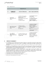
Page 29: ... LS fire damper a Make a visual inspection of the interior of fire damper determine the condition of the baffle and seal whether there are no damage or dirt that could block the fire baffle during closing b Check the wiring of the limit switches c Close the fire damper by pulling on the hand release The baffle should close freely Check that the baffle is closed properly If the baffle does not clos...

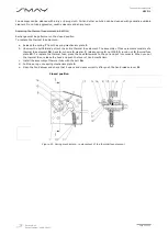
Page 30: ... bolt 14 and pull out the entire thermal fuse element The assembly of these elements consists of a thermal fuse element 16 hook 6 console 5 washer 7 release spring 9 nut M8 12 round nut 8 thermal fuse plate 13 To replace the thermal fuse press the hook 6 towards to the nut and put into console When you put the thermal fuse release the hook and push the lever of hand mechanism c Install the assembl...

Page 31: ...ntee for the delivered product for a period of 24 moths from the date of sale or another period agreed in the contract There is a possibility of extending the guarantee provided that a separate Maintenance and Service Agreement is signed between the manufacturer and the owner manager of the facility g The basis for complaint handling is to file a complaint within the warranty period within 7 days ...

Reviews: