background image


Version: 1.3 
Date: 31.03.2022 

Page 3 z 11 

Operation and Maintenance Manual 


CDH-F


1.


INTRODUCTION 


The  purpose  of  this  Operation  and  Maintenance  Manual  is  to  familiarize  the  user  with  the  intended  use,  design, 

operating principle, installation and operation of the product. 

2.


INTENDED USE 


CDH-F louvres are used for smoke and heat extraction in natural and mechanical smoke extraction systems. 

CDH-F-L  louvre  can  be  used  in  smoke  extraction  systems  as  a  wall  smoke  exhaust  device  with  the  possibility  of 

measuring  the  mass  flow  of  air  removed  by  the  extraction  louvre.  This  product  is  dedicated  to  staircases,  elevator 

shafts, wherever we want to know the mass flow of air being removed. 

3.


TECHNICAL DESCRIPTION 


CDH-F louvres are positioned by means of an electric actuator. The lamellas are made of anodised aluminum profiles 

and an insert mounted between profiles and secured with glazing gasket. In the S version the lamella insert is made of 

a 20 mm thick multi polycarbonate sheets. In the A version the lamella insert is made of 20 mm thick mineral wool 

with glass fleece inside and anodised sheet outside.  

The exhaust louvers frame is made of aluminum and powder coated in the RAL9006 matt color. 


CDH-F  electrical  control 

  the  lamellas  of  the  exhaust 

louvres  are  controlled  by  means  of  an  electric  actuator  of 

Belimo, open/close  type,  with  a return  spring, 24 V AC/DC 

or 230 V AC power supply.  

If an actuator with a return spring is in use, a power 

loss will open the louvre.     

The  wiring  diagram,  power  supply  and  control  parameters 

depend  on  the  type  of  the  electric  actuator  and  control 

system 

 see the data sheet of the selected actuator. 


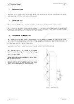
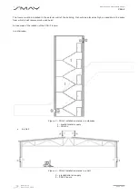
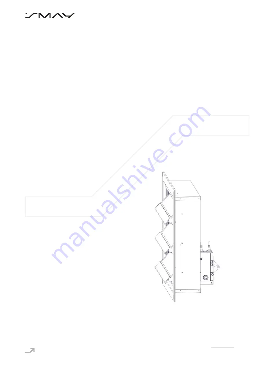
Figure 1 

CDH-F louvre.                   


Summary of Contents for CDH-F

Page 1: ...a v https www smay eu Operation and maintenance manual CDH F Smoke and heat wall exhaust ventilator ...

Page 2: ...Smay company reserves the right to modify this document Table of Contents 1 INTRODUCTION 3 2 INTENDED USE 3 3 TECHNICAL DESCRIPTION 3 4 INSTALLATION CONDITIONS 9 5 DISASSEMBLY OF THE ELECTRIC ACTUATOR 10 6 TRANSPORT AND STORAGE CONDITIONS 11 7 INSPECTION AND MAINTENANCE PROCEDURE 11 8 WARRANTY TERMS 11 ...

Page 3: ...o 17 1438 CPR 0534 PN EN 12101 2 2005 DUAL FUNCTION SMOKE EXTRACTION UNIT CDH F Technical characteristics of the external power source Power supply AC DC 24 V or AC 230 V Aerodynamic free area Aa 0 1 3 72 m2 Wind load class WL 1500 Reliability Re1000 Low ambient temperature T 15 Heat exposure B300 ...

Page 4: ...itioned by means of an electric actuator The lamellas are made of anodised aluminum profiles and an insert mounted between profiles and secured with glazing gasket In the S version the lamella insert is made of a 20 mm thick multi polycarbonate sheets In the A version the lamella insert is made of 20 mm thick mineral wool with glass fleece inside and anodised sheet outside The exhaust louvers fram...

Page 5: ...air being removed Figure 2 CDH F L design Figure 2 CDH F Lz design Tab 1 CDH F L and CDH F Lz description Lp Description 1 CDH F louvre 2 Telescopic duct section KT 3 Measuring strips 4 Panel with cable glands two glands for actuator cables two glands for copper tubes 5 Protective mesh ST STS4 with a perforated steel sheet with Hv20 hexagonal holes 6 The differential pressure transmitter is connec...

Page 6: ...ding It should be placed as high as possible in the space from which it will remove smoke and heat An example of the location of the CDH F louvre in a staircase Figure 3 CDH F installation places in a staircase 1 mechanical air supply 2 CDH F L in a hall Figure 4 CDH F installation places in a hall 3 gravitational air supply 4 CDH F louvre ...

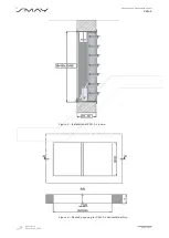
Page 7: ...Version 1 3 Date 31 03 2022 Page 6 z 11 Operation and Maintenance Manual CDH F Figure 5 Installation of CDH F L louvre Figure 6 Mounting opening for CDH F L horizontal battery ...

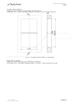
Page 8: ...battery installation opening 3095 65 2 1515 vertical mounting bar 65x40x2 L 2005mm 2 pcs on both sides of the wall Figure 7 Mounting opening for CDH F L vertical battery Vertical battery installation Example for max mounting opening of vertical battery 1515x4075 4075 65 2 2005 horizontal mounting bar 65x40x2 L 1515mm 2 pcs on both sides of the wall ...

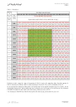
Page 9: ...39 1 47 1 54 10 6 11 9 13 9 15 2 16 5 17 8 19 1 20 4 21 7 23 0 24 3 25 6 26 9 28 2 29 5 30 8 32 1 33 4 8 1465 0 28 0 38 0 46 0 55 0 64 0 74 0 83 0 91 0 95 1 05 1 14 1 22 1 33 1 41 1 50 1 59 1 70 1 79 11 8 13 2 15 3 16 7 18 1 19 5 20 9 22 3 23 7 25 1 26 5 27 9 29 3 30 7 32 1 33 5 34 9 36 3 9 1640 0 32 0 42 0 52 0 62 0 72 0 83 0 93 1 04 1 09 1 18 1 30 1 40 1 49 1 59 1 71 1 81 1 91 2 01 12 9 14 5 16 ...

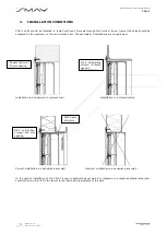
Page 10: ...lation in a brickwork or concrete wall Installation in a steel structure Correct installation in a sandwich panel wall Incorrect installation in a sandwich panel wall In the case of installation of the CDH F louver in sandwich panel wall it is necessary to prepare additional steel sub construction in order to fix the louver to the load bearing elements of the wall Dowels ø6 min 30 mm spacing Ø5 5 ...

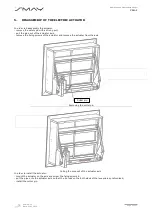
Page 11: ...ipe out of the actuator axis remove the fixing screws of the actuator and remove the actuator from the axis Removing the cotter pin Pulling the pipe out of the actuator axis In order to install the actuator mount the actuator on the axis and screw the fixing screws in put the pipe onto the actuator axis so that the tie rods on the both sides of the louver are synchronised install the cotter pin Co...

Page 12: ...l parts Carry out the opening and closing test of the unit lamellas If there is an actuator with a return spring mounted BFN BF turn off its power supply The outlet lover has to open Connect voltage to the louvre The outlet lover should close If the damper opens and closes correctly close it and leave in the closed position Of an open close actuator is installed BLE BE open the louver by means of ...

Reviews: