


6666
4.
4.
4.
4.
YOUR SMART WATCH
YOUR SMART WATCH
YOUR SMART WATCH
YOUR SMART WATCH™
™
™
™ UNIT
UNIT
UNIT
UNIT
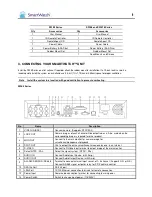
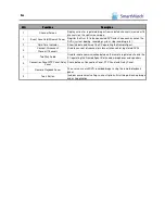
4.1 Front Panel
4.1.1. SWE4 Series
No.
Button
Function
1
CD-RW
Built-in CD-RW for recorded image backup.
2
Network LED
The LED is lit while the network client(s) (RemoteAgent) is connected to the system.
3
Sensor LED
The LED is lit when an active input is triggered.
4
HDD LED
Shows if the camera image is being stored onto or retrieved from the HDD (Hard
Disk Drive).
5
Power LED
Shows the Power status of the system. (GREEN: Working, RED: Stand-By).
6
USB Port
USB interface port for connecting external storage equipment.
7
Remote Controller
Receiver
Receives input signal from the IR Remote Controller.
8
Power Button
Used to turn the Power On/Off.
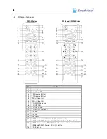
9
Select Channel (1~4 CH)
Images of corresponding input channel are displayed when channel number above
the arrow button is pressed. Used as cursor (for direction) in menu screen.
10
ENTER Button
Used to enter detail menu, go into the next stage, select or set value.
11
RETURN Button
Used to exit from the setting menu or to cancel setting value.
12
SETUP
A menu to enter setup mode.
13
Screen Mode Selection
Select between 1-screen mode and 4-screen mode.
14
SEQ Button
Automatic camera sequencing.
15
Playback
Playback recorded images.
16
Search
Search recorded images.
17
Shuttle
Shuttle (outer dial): speed up the playback speed of the image (1~32X).
18
Jog
Jog (inner dial): playback frame by frame.