


Installation
1) Turn off the circuit breaker (or remove fuses) supplying power to the switch location
2) Remove the existing wallplate from the switch you are replacing. Then, unscrew the switch and
remove it from the junction box.
3) Disconnect the wires from the switch you are replacing. If the wires cannot be detached by
unscrewing them, cut the wires where they enter the switch and then strip ½ inch of insulation off the
ends.
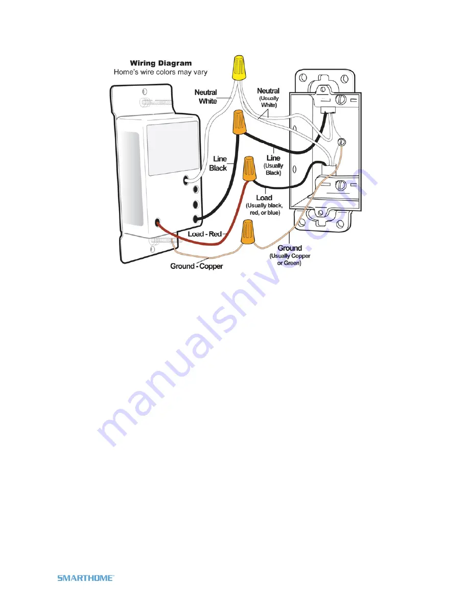
4) Identify the wires in the junction box using a voltage tester. Then, see the diagram above to identify
and connect the LINE, LOAD, NEUTRAL, and GROUND wires on X10 Dimmer Switch.
5) Ensure the wires are firmly attached and that there is no exposed copper except for the GROUND
wire
6) Gently place X10 Dimmer Switch into the junction box, orienting the unit with the LED on the left and
screw into place
7) Enable power to the switch from the circuit breaker or fuse panel
8) Test that the switch is working properly by turning the light on and off from the paddle
9) Reinstall the wallplate
Setting the X10 Address
1) Press & hold X10 Dimmer Switch’s Set button until X10 Dimmer Switch beeps
X10 Dimmer Switch’s LED will begin blinking
2) Using an X10 controller, send the X10 address you want to assign followed by the ON command
three times.
For example, to assign the address A1, send “A1 ON A1 ON A1 ON”.
X10 Dimmer Switch will
double-beep and its LED will stop blinking
Page 5 of 8 X10WS12A Rev: 10/7/2011 6:27 PM


