HAT552/HAT553
DUAL POWER ATS CONTROLLER
USER MANUAL
SMARTGEN (ZHENGZHOU) TECHNOLOGY CO., LTD.
Page 1: ...HAT552 HAT553 DUAL POWER ATS CONTROLLER USER MANUAL SMARTGEN ZHENGZHOU TECHNOLOGY CO LTD ...
Page 2: ...uding photocopying or storing in any medium by electronic means or other without the written permission of the copyright holder Applications for the copyright holder s written permission to reproduce any part of this publication should be addressed to Smartgen Technology at the address above Any reference to trademarked product names used within this publication is owned by their respective compan...
Page 3: ...TART STOP 14 8 2 AUTO START STOP 14 9 PARAMETER CONFIGURATION 15 9 1 ILLUSTRATION 15 9 2 PARAMETER CONFIGURATION TABLE 15 9 1 DIGITAL INPUT OUTPUT FUNCTION DESCRIPTION 19 10 EVENT LOG 21 11 SWITCH OPERATION RUNNING 22 11 1 MANUAL OPERATION RUNNING 22 11 2 AUTO OPERATION RUNNING 22 11 3 AUXILIARY CONTACT FEEDBACK INPUT OF SWITCH OPEN 26 12 COMMUNICATION CONFIGURATION AND CONNECTION 26 12 1 ILLUSTRA...
Page 4: ...ing one breaking and two breaking switches HAT552 HAT553 dual power ATS controller is made with the microprocessor in the core which can precisely measure 2 channel 3 phase voltages make correct judgment and control outputs for occurred voltage abnormal over voltage under voltage loss of phase over frequency under frequency reverse phase sequence It has compact structure advanced circuits simple w...
Page 5: ...on is used to prevent non professional error operations Commissioning can be done on site manually to execute genset start stop operations Switch Re closing function is fitted Breaker close output can be set to pulse or steady output 2 channel N wire isolated design Real time clock RTC display and event log function which can record 50 data cyclically Scheduled start stop generator function runnin...
Page 6: ... free output Dynamo Start Relay 8A AC250V Volts free output Digital Close Input Active when ASW1 and ASW2 short connected Active when BSW1 and BSW2 short connected Forced to Open Input GND connected is active not available for HAT552 Digital Input 1 GND connected is active Communication 1 1 RS485 isolated port MODBUS Protocol 2 D form USB port Case Dimensions 139mmx120mmx50mm Panel Cutout 130mmx11...
Page 7: ...1 A B power phase voltage 2 A B power line voltage 3 A B power voltage phase sequence 4 A B power frequency 5 Present continuous supply time 6 Last time continuous supply time 7 A power accumulated supply time 8 B power accumulated supply time 9 A power accumulated close times 10 B power accumulated close times 11 Close open status 12 Real time clock 13 Event log 14 Alarm information 15 Controller...
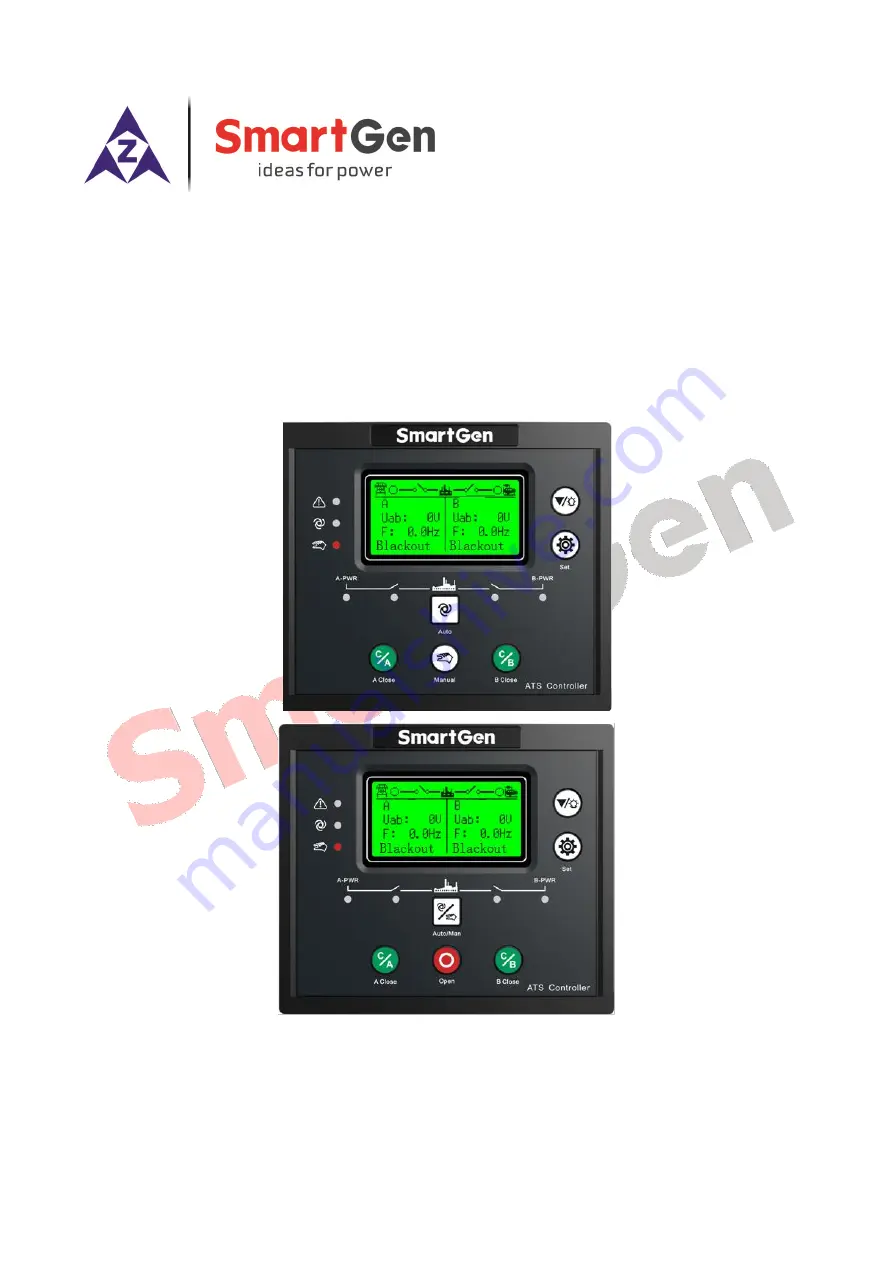
Page 8: ...HAT552 HAT553 DUAL POWER ATS CONTROLLER USER MANUAL HAT552 HAT553 ATS Controller 2020 05 14 Version 1 1 Page 8 of 35 6 OPERATING 6 1 OPERATION PANEL Fig 1 HAT552 Front Panel Fig 2 HAT553 Front Panel ...
Page 9: ... KEY FUNCTION DESCRIPTION Table 6 Key Function Description Key Function Description Manual Key Transfer to Manual mode HAT552 Auto Key Transfer to Auto mode HAT552 Manual Auto Key Transfer to Manual or Auto mode HAT553 A Close Key Active in manual mode Press and A power switch closes load is supplied by A power Open Key Active in manual mode Press and load is disconnected HAT553 B Close Key Active...
Page 10: ...larm status working status Supply system diagram Real time clock Status line is displayed on the first row of every page in main screen 7 2 SECOND LEVEL INTERFACE Table 8 Second Level Display Item Display Contents Parameter Settings AC Config Switch Config Genset Config Scheduler Config Digit Inputs Config Relay Outputs Config Module Config History Record Running mode transfer event Start stop eve...
Page 11: ... L3 Table 10 B Power Voltage Status No Item Description 1 B Available Delay for B power available detection 2 B Unavailable Delay for B power unavailable detection 3 Power Normal Power value is within normal range 4 Blackout Voltage is 0 5 Over Volt Voltage is above the pre set upper limit 6 Under Volt Voltage is less than the pre set lower limit 7 Over Frequency Frequency is above the pre set upp...
Page 12: ...s been open and load is disconnected When controller detects warning alarm warning alarm becomes active alarm indicator will slow flashes 1 time per second and when alarm disappears alarm indicator will extinguish Warning alarm isn t latched Table 13 Warning Alarm No Item Description 1 Forced to Open Forced to open Non fire cutoff input action is set to Warning when it is active the warning alarms...
Page 13: ...r Status Information No Item Description 1 Start Inhibit Genset start inhibit input is active 2 Remote Gen On Load Remote start onload input is active 3 Remote Gen Off Load Remote start offload input is active 4 Gen Start Mains NG Start when Mains is abnormal 5 Auto Mode Current is in auto mode 6 Manual Mode Current is in manual mode 7 4 MAIN MENU In main interface press key to enter main menu scr...
Page 14: ... REQUIREMENTS 8 2 1 1 INPUT PORT START Set Remote Start Onload or Remote Start Offload for configurable input ports and they are cannot be set at the same time Remote Start Onload Genset start outputs when generating is Ok GB closes when it is inactive disconnect genset start output signal Remote Start Offload Genset start outputs when mains is Ok MB closes when it is inactive disconnect genset st...
Page 15: ...ime from A power abnormal to normal 2 A Unavailable Delay 0 3600 s 5 The check time from A power normal to abnormal 3 B Available Delay 0 3600 s 10 The check time from B power abnormal to normal 4 B Unavailable Delay 0 3600 s 5 The check time from B power normal to abnormal 5 Set Master 0 1 0 0 A Master 1 B Master 6 System Type Set 0 2 0 0 A Mains B Gen 1 A Gen B Mains 2 A Mains B Mains 7 AC Syste...
Page 16: ...1 Enable 23 Phase Sequence Wrong 0 1 1 0 Disable 1 Enable 24 PT Fitted 0 1 0 0 Disable 1 Enable 25 PT Primary Volt 30 30000 V 100 26 PT Secondary Volt 30 1000 V 100 Switch Setting 1 Close Delay 0 1 20 0 s 5 0 Pulse time for close relay output continuous output when it is 0 2 Open Delay 0 1 20 0 s 5 0 Pulse time for open relay output continuous output when it is 0 3 Transfer Interval 1 9999 s 1 Wai...
Page 17: ...delay is over controller issues genset start signal 2 Genset Stop Delay 0 9999 s 5 Delay starts when genset prepares to stop when delay is over controller disconnects genset start signal Scheduled Start Stop Setting 1 Schedule Gen Enable 0 1 0 0 Disable 1 Enable 2 Schedule Load 0 1 0 0 Off Load 1 On Load 3 Schedule Period 0 2 0 0 Monthly 1 Weekly 2 Daily 4 Schedule Monthly Month January February M...
Page 18: ...ious Mode 1 Manual Mode 2 Auto Mode 2 Language 0 1 0 0 Simplified Chinese 1 English 3 Password 00000 65535 01234 Password for entering parameter setting 4 Module Address 1 254 1 Communication address for RS485 network 5 Com Baud Rate 0 3 2 0 2400bps 1 4800bps 2 9600bps 3 19200bps 6 Com USART_Parity 0 2 0 0 None 1 Odd Parity 2 Even Parity 7 Com Stop Bit 1 2 2 1 or 2 stop bits can be set 8 Date Time...
Page 19: ...panel Auto reset button is needed 12 B C Key Same as B Close key on the panel Auto reset button is needed 13 Open Key Same as Open key on the panel Auto reset button is needed 14 Man Mode Input Force controller mode to manual mode 15 Auto Mode Input Force controller mode to auto mode 16 Alarm Reset Input Reset current alarm 17 Remote Ctrl Inhibit Remote operation is inactive when this is active 18...
Page 20: ...7 Breaking Compulsory Output when Forced to Open is active HAT553 18 A Close Control Control A switch to close 19 A Open Control Control A switch to open HAT553 20 B Open Control Control B switch to close 21 B Open Control Control B switch to open HAT553 22 Open Control Control A and B switches to open HAT553 23 Reserved 24 Reserved 25 A Closed Input A switch closed status is outputted when switch...
Page 21: ... item via Down key When recorded items are over 50 new item will cover the newest record Record type includes Action Event Warn Event Fault Event Fault events are all fault alarms warn events are all warning alarms Table 20 Action Events No Action Event Description 1 Closing A Record when A power close is outputted 2 Closing B Record when B power close is outputted 3 Opening A Record when A power ...
Page 22: ...inated always Table 21 Manual Transfer Key Icon Key Name Function Description A Power Close Press and if load is in open status A power closes and load is supplied by A power B Power Close Press and if load is in open status B power closes and load is supplied by B power Open Key Press and load is disconnected HAT553 11 2 AUTO OPERATION RUNNING Press manual auto transfer key and auto status indica...
Page 23: ...1 Page 23 of 35 11 2 1 AUTO TRANS RESTORE When Auto Trans Restore is set A power is master if A power is normal then A power closes if A power is abnormal B power is normal then A power opens B power closes if A power recovers normal then B power opens A power closes Fig 3 Auto Trans Restore Flow Chart ...
Page 24: ...UTUAL BACKUP When Auto Trans Non Restore is set and Mutual Backup is active A power is master If A power is normal then A power closes if A power is abnormal B power is normal then A power opens and B power closes If A power recovers normal B power is normal then switch keeps at B power close status Fig 4 Auto Trans Restore Active for Mutual Backup Flow Chart ...
Page 25: ...fer to manual mode and by button operation close otherwise in auto mode switch only transfers between open and backup power B power position 11 2 4 NONE OPEN TRANSFER When none open transfer is enabled controller will not execute open operation Detailed setting method in parameter setting interface enter switch setting interface find None Open Transfer Enable and set it enabled The following illus...
Page 26: ...ansfer controller has RS485 communication port USB communication port Between them RS485 communication port allows to connect LAN of open structure Communication port applies Modbus communication protocol by the running software on PC or data collecting system to provide a simple and practical dual power transfer management method of factories telecommunication industries and civil buildings reali...
Page 27: ...53 DUAL POWER ATS CONTROLLER USER MANUAL HAT552 HAT553 ATS Controller 2020 05 14 Version 1 1 Page 27 of 35 13 DEFINITION OF CONNECTING TERMINALS 13 1 DESCRIPTION OF CONNECTING TERMINALS Fig 7 Controller Back Panel ...
Page 28: ...d BN 14 S 15 T 16 BN 17 AUX OUTPUT Programmable output 1 Default common alarm output N O output capacity 8A 250VAC 18 19 GENSET START Genset start control output port N C output capacity 8A 250VAC 20 21 A RS485 communication port 120 Ω Resistor for impedance matched has been connected inside 22 B 23 120Ω Resistor RS485 impedance matched resistor Users need to connect this terminal to Terminal 21 b...
Page 29: ... 2020 05 14 Version 1 1 Page 29 of 35 13 2 DESCRIPTION OF CONTROLLER SUPPLY Controller is AC supplied by the two AC sampling terminals directly Fig 8 AC Supply Diagram 13 3 DESCRIPTION OF RS485 CONNECTION Connecting of RS485 and Adapter is like below Fig 9 RS485 Connecting Diagram ...
Page 30: ...T552 HAT553 ATS Controller 2020 05 14 Version 1 1 Page 30 of 35 14 TYPICAL WIRING DIAGRAM Fig 10 SGQ N T Application Diagram Table 23 Related Settings A Part of Parameter Setting Switch Type Setting No breaking available for HAT553 not available for HAT552 ...
Page 31: ...R ATS CONTROLLER USER MANUAL HAT552 HAT553 ATS Controller 2020 05 14 Version 1 1 Page 31 of 35 Fig 11 FEITENG Application Diagram Table 24 Related Settings A Part of Parameter Setting Switch Type Setting Two breakings HAT553 ...
Page 32: ...ller 2020 05 14 Version 1 1 Page 32 of 35 Fig 12 Connector Application Diagram Table 25 Related Settings A Part of Parameter Setting Switch Type Setting Two breakings HAT553 Close Time Set it to 0 HAT553 Switch Transfer Interval 10s HAT553 set it according to factual occasions ...
Page 33: ...nnect wires based on the real occasions Attached illustration for LO NO connection inside controller HAT553 HAT552 controller has automatic transfer function of ATS power supply inside Only if one voltage of A power and B power is normal by transfer between N O contact and N C contact of intermediate relay 1 and intermediate relay 2 ensure ATS power supply normal The output is LO NO Output value i...
Page 34: ...LER USER MANUAL HAT552 HAT553 ATS Controller 2020 05 14 Version 1 1 Page 34 of 35 15 INSTALLATION The controller is designed by panel installation method and is fixed by clips for installation Fig 15 Overall Dimensions and Cutout Unit mm ...
Page 35: ...RS485 Auxiliary Output Error Check auxiliary output connecting wire pay attention to N O N C points Check output port setting function and output type in parameter settings Auxiliary Input Abnormal Check whether aux input port is GND connected when it s active and it shall hung up when it is inactive NOTE The input port will be possibly destroyed when connected with voltage Check the input setting...