2
5
Inputs/Outputs: Enter the number of Inputs/Outputs your SuperMatrix has. For
now we will assume that there are 16 inputs and 16 outputs.
Com Port: Select the appropriate com port that your computer is using to access
the router.
Router Timeout: By default this is 0 meaning the computer acknowledges
commands almost instantly. Sometimes a computer takes longer to respond. This
setting should be left at 0. If you need to change it, it should be no higher than
0.2.
After you have entered in the necessary information click OK.
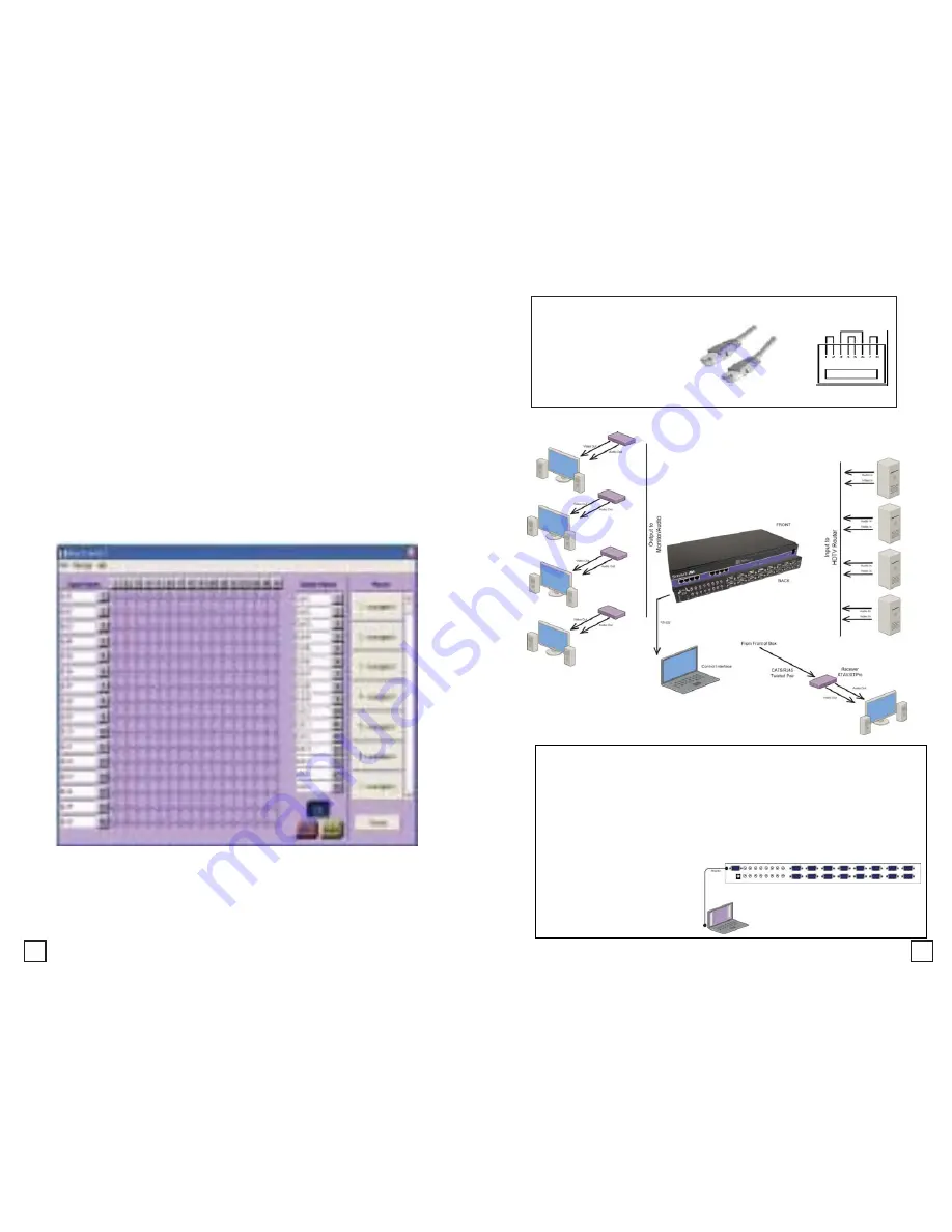
This will now take you to the Main Routing Window where you can route the
different video/audio connections.
On this screen you will notice the input buttons running down the left side while
the output buttons run across the top. They are each labeled 1 through 16.
Note: The three small colored buttons at the lower right labeled ALL, VIDEO, and
AUDIO are not available if AV Split was not checked when you configured your
router.
The Main Routing Window enables you to control the router(s) connections by
means of the matrix panel, the button panel, or with pre-recorded routes called
macros.
Matrix Panel: This is probably the simplest way to route the connections. Simply
click on the cross point itself. The input on the left will then be routed to the
output above.
Software Installation & Operation
Installation Diagram’s
HDTVRouter Installation Diagram
Preparing & Connecting System CAT5 Cable
Following is the wiring standard for terminating CAT 5 cable
using RJ-45 connector:
Pair 1 Pins 1 & 2
Pair 2 Pins 3 & 6
Pair 3 Pins 4 & 5
Pair 4 Pins 7 & 8
Connectors: RJ-45
Capacitance: 14 pf/ft (46.2 pf/m)
Conductor Gauge: 24 AWG
Connecting the Communication Cable: RS-232
Each unit can be controlled by a RS-232 port connected from the back of the
chassis. The SmartControl software will be used to control the units.
1. Connect the RS-232 cable the control computer by connecting the
female RS-232 connector into the male RS-232 connector of the PC.
Turn the side screws so that it does not accidentally become
disconnected
2. Connect RS-232 cable connector to the male RS-232 connector on
the back of the chassis.


