background image


Content 

1.


PRODUCT OVERVIEW ............................................................................................................... 3


1.1.


G

ENERAL INTRODUCTION

 ............................................................................................................... 3


1.2.


P

RODUCT FEATURES

 ...................................................................................................................... 3


1.3.


P

RODUCT SPECIFICATIONS

 ............................................................................................................... 4


2.


PRODUCT APPEARANCE AND SIGNAL CONNECTION ................................................................. 5


2.1.


P

RODUCT APPEARANCE

 .................................................................................................................. 5


2.2.


S

IGNAL CONNECTION

 ..................................................................................................................... 6


3.


INSTALLATION AND TESTING .................................................................................................... 7


3.1.


D

RIVER INSTALLATION

 .................................................................................................................... 7


3.2.


S

OFTWARE INSTALLATION

................................................................................................................ 8


3.3.


V

OLTAGE SIGNAL TEST

 .................................................................................................................... 8


3.4.


T

EMPERATURE SIGNAL TEST

 ........................................................................................................... 11


3.5.


D

ATA FILE DETAIL

 ......................................................................................................................... 14


4.


PROGRAMMING GUIDE ......................................................................................................... 15


4.1.


O

VERVIEW

 ................................................................................................................................. 15


4.2.


G

ENERAL COMMANDS

 ................................................................................................................. 15


4.3.


S

ETTING COMMANDS

 ................................................................................................................... 15


4.4.


M

EASUREMENT COMMANDS

 ......................................................................................................... 16


5.


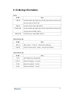
ORDERING INFORMATION ..................................................................................................... 17


6.


SERVICE AND WARRANTY ...................................................................................................... 18


7.


REVISION HISTORY ................................................................................................................. 19


Summary of Contents for PS2016 Series

Page 1: ...PS2016 Series High Precision Isolated Data Collector PS2016V PS2016I PS2016V 485 PS2016I 485 User Manual Rev D Beijing Smacq technologies Co Ltd www smacq com www smacq cn...

Page 2: ...5 2 2 SIGNAL CONNECTION 6 3 INSTALLATION AND TESTING 7 3 1 DRIVER INSTALLATION 7 3 2 SOFTWARE INSTALLATION 8 3 3 VOLTAGE SIGNAL TEST 8 3 4 TEMPERATURE SIGNAL TEST 11 3 5 DATA FILE DETAIL 14 4 PROGRAMM...

Page 3: ...test tasks at very low cost and complete the task with very high efficiency 1 2 Product features up to 4 digit reading resolution and 0 015 DC voltage accuracy Max 200V DC voltage range DC voltage me...

Page 4: ...ns Model PS2016V PS2016V 485 PS2016I PS2016I 485 Parameters Voltage Temperature Thermocouple Current Resolution 4 Digit Basic accuracy reading digits Voltage 0 02 4 0 05 4 Temperature Thermocouple K 2...

Page 5: ...ions Refer to chapter 2 1 dimensions diagram Weight Without screw terminals 500g With screw terminals 525g Working environment Temperature 0 C to 50 C Relative humidity 5 to 80 No condensation Storage...

Page 6: ...ow its pin distribution and the corresponding signal in detail Diagram 2 Screw terminal connector corresponding signals Name Notes ch ch0 to ch15 is the signal positive input of channel 0 to 15 ch ch0...

Page 7: ...eries DAQ driver on the Resources CD double click the file SETUP EXE then click Install and there will be a dialog of success after the driver is installed After correctly installing the driver Window...

Page 8: ...e software click Next all the way till it s installed Usually you can keep the default installation directory Start the software after the installation Figure 4 shows the software interface 3 3 Voltag...

Page 9: ...ng cycle in seconds 3 Set the range Can be set as 20V or 200V range when measuring voltage signals 4 Set the path of data storage 5 Choose the channel to run the DAQ device in Figure 5 Voltage signal...

Page 10: ...esponding channel legend display In the trend graph display the ordinate scale value is automatically scaled by default You can cancel the automatic Y scale adjustment by right clicking the pop up men...

Page 11: ...uring range is 1100 When using other types of thermocouples the maximum measuring range is the temperature range corresponding to 45 108mV on its indexing table Figure 7 Voltage test acquisition inter...

Page 12: ...ure 9 with detailed notes below 1 Choose correct serial port number 2 Set sampling cycle measured in seconds 3 Set range Choose thermocouple range when measuring temperature and choose corresponding t...

Page 13: ...esponding channel legend display In the trend graph display the ordinate scale value is automatically scaled by default You can cancel the automatic Y scale adjustment by right clicking the pop up men...

Page 14: ...ed in csv format readable by Microsoft Excel as shown in Figure 11 below The data file consists of beginning time cycle measuring type and all original data for this acquisition Figure 10 Temperature...

Page 15: ...S 485 interface If your PS2016 DAQ device is equipped with RS 485 interface it has a default baud of 9600 8 bit data bits 1 stop bit no hardware handshake and its command starts from 1 byte address wi...

Page 16: ...ement commands CH n V Read measured voltage from specified channel with return value measured in V The value of n ranges from 0 to 15 corresponding to channel 0 to channel 15 For example USB send CH0...

Page 17: ...ermocouple measurement with cold end compensation RS485 interface PS2016I 485 16 channel current input RS485 interface Optional accessories Model Notes USB A B USB connector 1 5 meters USB A type to U...

Page 18: ...details Unless otherwise provided in this manual or warranty statement Smacq does not provide any other warranties either express or implied If you need technical support or more service details or if...

Page 19: ...setting for every channel in software PS2016 DAQ Lite 2 K type thermocouple supports measuring up to 1100 2017 3 30 Rev C Change RS 485 connector pin detail to correspond to the changes in products wi...

Reviews: