background image

SMA


Technologie AG

Installation Requirements

Installation manual

SC-100-13:SE2407

Page 19

5.1.4 Ventilation

Ambient Temperature / Air Quality / Humidity

To cool the inverter, the ventilation system must be free of any obstructions in order to
ensure the required inlet ventilation and  heat dissipation.
The specified minimum clearances in 

Appendix C

 must be maintained for this purpose.

For safe operation, and maximum feed-in performance, the permissible ambient
temperature is between -20 and +50 °C. The rated values can be ensured at ambient
temperatures of up to +40 °C.
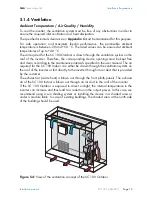
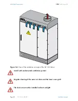
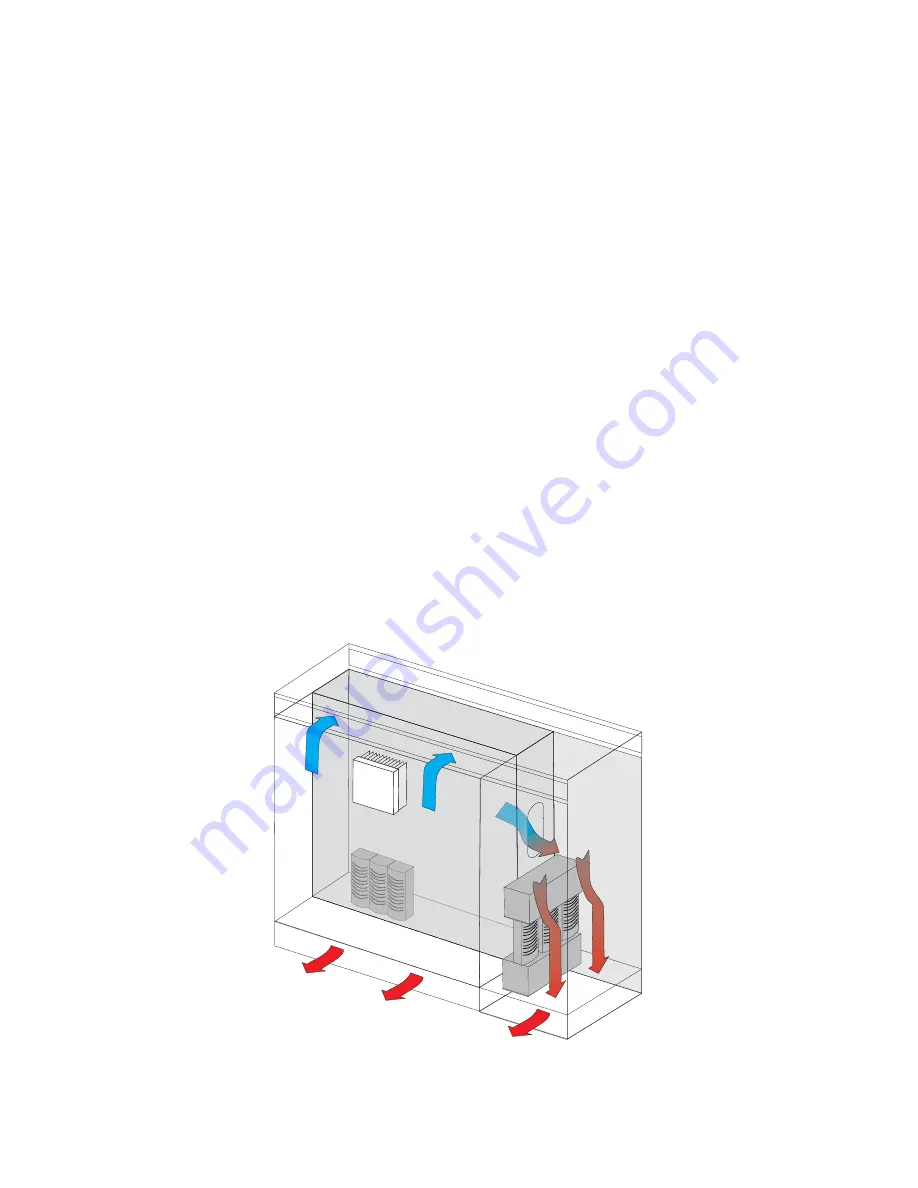
The air required for the SC 100 Outdoor is drawn through the ventilation system on the
roof of the inverter. Therefore, the corresponding device openings must be kept free
and clean according to the maintenance intervals specified in the user manual. The air
required for the SC 100 Indoor can either be drawn through the ventilation system on
the roof of the inverter or fed directly to the inverter through an air duct that is provided
by the customer.
The exhaust air (waste heat) is blown out through the front plinth panels. The exhaust
air of the SC 100 Indoor is blown out through an air duct in the roof of the inverter.
If the SC 100 Outdoor is exposed to direct sunlight, the internal temperature in the
inverter can increase and thus lead to a reduction in the output power. In this case, we
recommend using a sun shading system or installing the device in a shaded area or
under a module table. In case of existing buildings, the shaded area at the north side
of the building should be used.

Figure 5.4:

 View of the ventilation concept of the SC 100 Outdoor

Summary of Contents for Sunny Central SC 100

Page 1: ...Sunny Central SC 100 Installation manual Installation manual Version 3 0 SC 100 13 SE2407 IME SCO...

Page 2: ......

Page 3: ...this Manual 6 3 4 Checking and Storage 6 3 5 Transport 6 3 6 Installation 7 3 7 Special Hazards of Photovoltaic Systems 7 3 8 Electrical Connection 8 3 9 Operation 9 3 10 Commissioning Maintenance an...

Page 4: ...7 1 2 AC Control Voltage Connection Optional 27 7 1 3 Handling the Connection Terminals 29 7 1 4 Sensors and Digital Outputs 29 7 1 5 Inverter Communication Connection 30 7 1 6 Shield Contact Handlin...

Page 5: ...nd commission the inverters The instructions assume that you the installer are familiar with electrical installations and know the corresponding rules and regulations 1 3 Explanation of the Symbols Us...

Page 6: ...rect connection and reliable operation of the device please take note of the safety and installation instructions in the following sections The following extra documents are also available in addition...

Page 7: ...de relating to transport installation electrical connection and commissioning of the equipment Any deviation from the installation guide instructions is regarded as inappropriate use of the equipment...

Page 8: ...o the device and or unclear delivery contents please contact SMA Technologie AG immediately contact address is in the appendix 3 5 Transport Only the transport methods described in the installation gu...

Page 9: ...the photovoltaic generator and or the Sunny Central This is especially important to note when disconnecting particular parts of the system Very high DC voltages are present no zero crossing which in...

Page 10: ...ightning Overvoltage Protection The device has internal overvoltage protection on the DC side and depending on the option chosen also has lightning and or overvoltage protection on the AC side The des...

Page 11: ...ese power sources are secured against being switched on again and when it has been checked that the device is voltage free Only qualified technical personnel who are familiar with the operation of the...

Page 12: ...touching The nominal voltage frequency and the right hand rotary field are maintained see device technical data The polarity of the DC voltage at the inputs fuse inputs device dependent has been chec...

Page 13: ...ower circuit from the grid and the photovoltaic generator The protective ground connection must be made before the external voltage is switched on The nominal voltage frequency and right hand rotary f...

Page 14: ...taken in exactly the same manner as prescribed for commissioning maintenance and repair work Hearing Protection The device fans and the power unit create significant levels of operating noise In addit...

Page 15: ...ng the device depending on the operating conditions certain components can be very hot e g fuses transformer core sine wave filter heatsinks etc Safety gloves should always be worn when working near c...

Page 16: ...o assist with transporting the data sheet on the dimensions and weight is contained in Appendix B The center of gravity of the cabinet unit is marked on the outside of the packaging 4 2 Transport Poss...

Page 17: ...ent temperature air quality humidity 5 1 Installation Site Requirements 5 1 1 Foundation The foundation must guarantee solid and safe positioning of the inverter It must provide the load carrying capa...

Page 18: ...ep in mind that the cables and conduits should enter the inverter from underneath This means that suitable conduits or cable feed throughs should be installed prior to pouring Pouring and structural i...

Page 19: ...nt cable feeds from the front and from the rear the cable must be routed into the foundation plate from below Dimensioning the concrete foundation and cable feed pipes through the concrete foundation...

Page 20: ...corresponding dimensions are contained in Appendix C 5 1 3 Inverter Protection Rating EMC Sound Levels The outdoor version of the Sunny Central SC 100 is suitable for outdoor installation according t...

Page 21: ...ings must be kept free and clean according to the maintenance intervals specified in the user manual The air required for the SC 100 Indoor can either be drawn through the ventilation system on the ro...

Page 22: ...13 SE2407 Installation manual Figure 5 4 View of the ventilation concepts of the SC 100 Indoor Install with unobstructed ventilation system Regular cleaning of the outer air inlets and the inner cove...

Page 23: ...4S2 and 4C1 whereas the inlet air for the SC 100 Indoor must satisfy the requirements of the classifications 3S2 and 3C1L The operation of the inverter is suited to a relative humidity of 15 to 95 Th...

Page 24: ...chors threaded bolts must be in place before installation A rig close to the base of the device facilitates its attachment to the foundation The corresponding figure is found in Appendix D After attac...

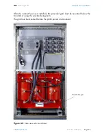
Page 25: ...al SC 100 13 SE2407 Page 23 After the cabinet has been installed the provided grid must be mounted below the transformer using the provided wing bolts The grid must be mounted before the plinth panels...

Page 26: ...Grid Power Connections The AC grid connection is made at the TN C TN S TT grid connection type which must be provided by the customer using a 3 phase system equipped for 400 V The connection terminals...

Page 27: ...ng and the SC100 electrical connections Ensure the grid connection cable is fused at the nominal current indicated on the name plate If the specified nominal current differs from the nominal current o...

Page 28: ...Electrical Connection SMA Technologie AG Page 26 SC 100 13 SE2407 Installation manual Figure 7 2 Differnet kind of AC grid connection terminals...

Page 29: ...l source The connection to the control voltage supply is made 1 phase to a TN S grid connection The standard bridges in the connection terminal strip as shown in the wiring diagram must therefore be r...

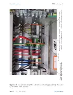
Page 30: ...al for external control voltage optional the sensor inputs and the communication Connection terminals for external control voltage with plugged bridges NET connection Sensor inputs to be equipped opti...

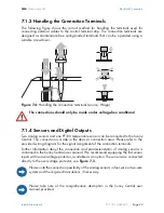
Page 31: ...Sunny Central The connection is made in the device s connection area Please refer to the provided wiring diagram for the signal assignment of the connection terminals Further information about the con...

Page 32: ...en planning or establishing the communication An optimum and project related plan for the data transfer should be coordinated with SMA 7 1 6 Shield Contact Handling Instructions The external signal an...

Page 33: ...the Sunny String Monitors is protected Optionally the analog signal input of an external temperature sensor see wiring diagram can also be protected against lightning and overvoltage If the control vo...

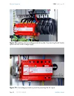
Page 34: ...G Page 32 SC 100 13 SE2407 Installation manual Figure 7 8 Lightning and overvoltage protection system for protecting the AC feed in system and the control voltage supply Figure 7 9 Overvoltage protect...

Page 35: ...well Before measuring the insulation the overvoltage protectors must be removed or disconnected or the existing fuses must be removed We recommend using lightning and overvoltage protection for the ex...

Page 36: ...he cabinet Suitable cable screw connections must be installed in the removable base plates to provide strain relief for the cable A variety of threaded joint sizes is provided for this purpose The DC...

Page 37: ...SMA Technologie AG Electrical Connection Installation manual SC 100 13 SE2407 Page 35 Figure 7 5 View of the DC connection area...

Page 38: ...and L3 The level of the AC voltage should be measured and logged The Sunny Central feeds into the grid using 3 x 400 V 10 AC Control Voltage Connection Optional The connection made to the feed in cab...

Page 39: ...cuit breakers and motor overload switches in the Sunny Central are to be switched on Now the inverter is completely connected on the AC and DC sides and can be switched on using the key switch Close t...

Page 40: ...th the international center of gravity symbol see figure A The symbols shall be sprayed on using a stencil In addition transport instructions shall be affixed to the inverter see figure A The transpor...

Page 41: ...l SC 100 13 SE2407 Page 39 Figure A Transport instructions for Sunny Central SC inverters Forbidden Permitted and must be observed Tilting Center of gravity marking Suspending from eyelets Crane fork...

Page 42: ...pple PV voltage UPP 3 Number of DC inputs terminal not secured 3 x positive 120 mm M12 screws 3 x negative 120 mm M12 screws Output data Nominal AC output power PAC 100 kW Operating grid voltage 10 UA...

Page 43: ...SCC Sunny Central Control interfaces Communication optional Analog ISDN Ethernet GSM Analog inputs optionally1x Pt100 2x Ain b Overvoltage protection for analog inputs optional Sunny String Monitor in...

Page 44: ...ent conditions Protection rating per EN 60529 IP44 IP54 Permissible ambient temperature T 20 C 50 Cc Relative humidity not condensing Uair 15 95 Max altitude above sea level NN 1 000 m Air quality min...

Page 45: ...ple PV voltage UPP 3 Number of DC inputs terminal not secured 3 x positive 120 mm M12 screws 3 x negative 120 mm M12 screws Output data Nominal AC output power PAC 100 kW Operating grid voltage 10 UAC...

Page 46: ...SCC Sunny Central Control interfaces Communication optional Analog ISDN Ethernet GSM Analog inputs optionally1x Pt100 2x Ain b Overvoltage protection for analog inputs optional Sunny String Monitor i...

Page 47: ...mbient conditions Protection rating per EN 60529 IP21 Permissible ambient temperature T 20 C 50 Cc Relative humidity not condensing Uair 15 95 Max altitude above sea level NN 1 000 m Air quality minim...

Page 48: ...Page 46 SC 100 13 SE2407 Installation manual 11 Appendix C Extract from the SC installation requirements SC 100 Outdoor installation requirements Concrete foundation slab Front view Concrete foundatio...
Page 49: ...echnologie AG Appendix C Installation manual SC 100 13 SE2407 Page 47 SC 100 Outdoor installation requirements Cable section option customer Front view Cable section option customer SC 100 indoor Side...
Page 50: ...DC AC mm mm mm mm mm mm mm kg m h SC 100 Indoor oben Top 805 1610 50 50 1 50 850 925Kg 2300m h M12 2 185mm 3 SC 100 Outdoor unten Base 870 1850 500 500 600 500 850 925Kg 2300m h M12 2 185mm 3 1 in Ab...

Page 51: ...ogie AG Appendix D Installation manual SC 100 13 SE2407 Page 49 12 Appendix D Illustration of SC100 Outdoor Base Attachment RITTAL R Branz 12 01 2007 Steuerkabel AC Kabel Kabeleinf hrung DC Kabel Kabe...
Page 52: ...Appendix D SMA Technologie AG Page 50 SC 100 13 SE2407 Installation manual...

Page 53: ...otection conditions Altering the product or supplied software without authority The product malfunctions due to operating attached or neighboring devices beyond statutory limit values In case of unfor...

Page 54: ...gy for the Success of Photovoltaics SMA Ib rica Tecnolog a Solar S L Barcelona Spain E mail info SMA Iberica com SMA Italia S r l Milan Italy E mail info SMA Italia com SMA France S A S Lyon France E...

Reviews: