background image

Mounting

SMA America, LLC

18

SB8-10TL-IUS103811

Installation Guide

5 Mounting

5.1 Safety

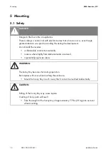
DANGER

Danger to life due to fire or explosions.
There is always a certain risk with electric devices that a fire can occur, even though 
greatest attention was paid to avoiding this during the development.
Do not install the inverter:

• on flammable construction materials,
• in areas where highly flammable materials are stored,
• in potentially explosive areas.

WARNING

The Sunny Boy becomes hot during operation.
Burn injuries will occur when touching the enclosure.

• Mount the Sunny Boy in such a way that it cannot be touched inadvertently.

CAUTION

Falling of the Sunny Boy may cause injuries.
Crushing of body parts will result.

• Take the weight of the Sunny Boy of approximately 77 lbs. (35 kg) into account 

when mounting.

Summary of Contents for SUNNY BOY 10000TL?US

Page 1: ...SB8 10TL IUS103811 IMUS SB8 10TLUS Version 1 1 US PV Inverter SUNNY BOY 8000TL US 9000TL US 10000TL US Installation Guide...

Page 2: ......

Page 3: ...cumstances The exclusion of implied warranties may not apply in all cases under some statutes and thus the above exclusion may not apply Specifications are subject to change without notice Every attem...

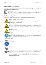
Page 4: ...carefully read and follow all instructions cautions and warnings in this installation manual Warnings in this document A warning describes a hazard to equipment or personnel It calls attention to a p...

Page 5: ...arc hazards The product has large electrical potential differences between its conductors Arc flashes can occur through air when high voltage current flows Do not work on the product during operation...

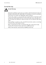
Page 6: ...parts except for the fans on the bottom of the enclosure and the filters behind the fans as well as the handle covers on the sides of the unit For all repair and maintenance always return the unit to...

Page 7: ...1 Parts of the Sunny Boy 15 3 2 Position of the Labels 15 3 3 Identifying the Sunny Boy 16 4 Unpacking and inspection 17 4 1 Scope of delivery 17 5 Mounting 18 5 1 Safety 18 5 2 Selecting the mounting...

Page 8: ...6 DC connection 37 6 6 1 DC connection requirements 38 6 6 2 Connecting the DC cable 38 6 7 Communication 41 7 Commissioning 42 7 1 Display 43 7 2 LED Display 45 7 3 Setting the display language 47 8...

Page 9: ...ng the Sunny Boy and SMA DC Disconnect 58 11 2 Packaging 59 11 3 Storage 59 11 4 Disposal 59 12 Technical data 60 12 1 Sunny Boy 8000TL US 60 12 2 Sunny Boy 9000TL US 62 12 3 Sunny Boy 10000TL US 64 1...

Page 10: ...Table of Contents SMA America LLC 10 SB8 10TL IUS103811 Installation Guide...

Page 11: ...he equipment 1 2 Target group This manual is for qualified personnel Qualified personnel have received training and have demonstrated skills and knowledge in the construction and operation of this dev...

Page 12: ...frame of the PV modules If you connect grounded modules to the Sunny Boy the error message F Riso is displayed During operation the DC circuit is connected to the AC grid House grid Energy flows into...

Page 13: ...ation Do not connect any sources of energy other than PV modules to the Sunny Boy Position Description A PV modules B Sunny Boy Combiner Box C Sunny Boy with SMA DC Disconnect D AC load circuit breake...

Page 14: ...urer void the warranty claims and operation permission 2 2 Safety instructions The Sunny Boy 8000TL US 9000TL US and 10000TL US is a transformerless inverter That is why it has no galvanic separation...

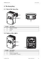
Page 15: ...Guide SB8 10TL IUS103811 15 3 The Sunny Boy 3 1 Parts of the Sunny Boy 3 2 Position of the Labels Position Description A Ergonomic handles B Display C Fans Position Description A Type label B General...

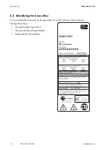
Page 16: ...Installation Guide 3 3 Identifying the Sunny Boy You can identify the Sunny Boy by the type label It is on the right side of the enclosure The type label shows The serial number Serial No The type of...

Page 17: ...f it becomes necessary to return the Sunny Boy use the original packing material 4 1 Scope of delivery Position Number Description A 1 Sunny Boy B 1 Wall mounting bracket C 1 Spare screw and spare was...

Page 18: ...install the inverter on flammable construction materials in areas where highly flammable materials are stored in potentially explosive areas WARNING The Sunny Boy becomes hot during operation Burn in...

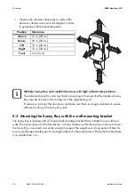
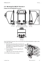
Page 19: ...sible at all times Vertical installation or tilted backwards by max 15 The connection area must point downwards Never install the device with a forward tilt Do not install horizontally Install at eye...

Page 20: ...on is plumb and sturdy enough to support the weight over a long period of time Be sure to use the appropriate type of mounting hardware for the wall material Ensure that the hardware is no smaller tha...

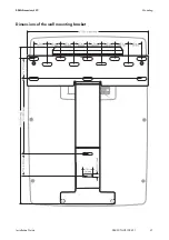
Page 21: ...SMA America LLC Mounting Installation Guide SB8 10TL IUS103811 21 Dimensions of the wall mounting bracket...

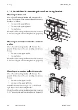
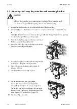
Page 22: ...on a pillar Attach the wall mounting bracket with 3 screws The position of the screws on the wall mounting bracket is as follows 2 screws on the upper middle 1 screw below Mount the wall mounting bra...

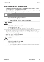
Page 23: ...holes in horizontal or vertical position of the bracket see chapter 5 3 1 Possibilities for mounting the wall mounting bracket page 22 4 Remove the bracket and drill holes at the marks 5 Insert wall...

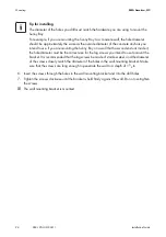
Page 24: ...y Boy For example if you are mounting the Sunny Boy to a concrete wall the hole diameter should be approximately the same as the outside diameter of the concrete anchors you intend to use If you are m...

Page 25: ...s of the wall mounting bracket using two screws and washers provided 1 Place the screws and the washers in the holes in the fastening tabs on the DC Disconnect The teeth on the washers must lie agains...

Page 26: ...the Sunny Boy into account when mounting 3 Hook the Sunny Boy using the enclosure opening in the back plate into the wall bracket 4 Inspect the Sunny Boy from both sides to ensure that it sits center...

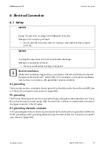
Page 27: ...ctor may be required by the Authority Having Jurisdiction AHJ Use the PV grounding and DC grounding electrode conductor terminal see 6 4 Sunny Boy connection area overview page 30 NOTICE Ingress of wa...

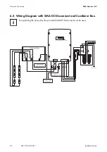
Page 28: ...rical Connection SMA America LLC 28 SB8 10TL IUS103811 Installation Guide 6 2 Wiring Diagram with SMA DC Disconnect and Combiner Box For operating the Sunny Boy the provided SMA DC Disconnect must be...

Page 29: ...PV modules with opaque material 7 Pull the AC and DC cables through the cable conduits into the SMA DC Disconnect The cables are inserted into the SMA DC Disconnect NOTICE Ingress of water when mounti...

Page 30: ...ica LLC 30 SB8 10TL IUS103811 Installation Guide 6 4 Sunny Boy connection area overview In the following overview illustration there is a schematic representation of the connection area of an open Sun...

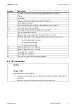
Page 31: ...als N L1 and L2 I Varistor terminal with varistors K SMA DC Disconnect Output AC line terminals N L1 and L2 L SMA DC Disconnect Grounding electrode terminal for the connection of Grounding electrode c...

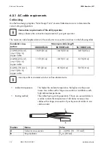
Page 32: ...94 F 90 C copper cable 184 ft 56 m 164 ft 50 m 148 ft 45 m 4 AWG 25 mm 194 F 90 C copper cable 115 ft 35 m 103 ft 31 m 92 ft 28 m 6 AWG 16 mm 194 F 90 C copper cable 72 ft 22 m 65 ft 20 m 58 ft 18 m U...

Page 33: ...of fire due to overcurrent Death or serious burn injuries will result When a Sunny Boy and a consumer are connected to the same line circuit breaker the protective function of the line circuit breake...

Page 34: ...nsert the cable into the SMA DC Disconnect page 29 8 Place the cover back onto the fuse box 9 Tighten the screws 10 Open the DC Disconnect as described in section 8 3 Opening SMA DC Disconnect page 50...

Page 35: ...minal The AC cables are now connected in the SMA DC Disconnect 6 5 3 Connecting the AC cable in the Sunny Boy 1 Open the Sunny Boy as described in section 8 1 Opening the Sunny Boy page 48 15 Connect...

Page 36: ...fixed in the terminal 10 Close the SMA DC Disconnect as described in section 8 4 Closing SMA DC Disconnect page 51 11 Close the Sunny Boy as described in section 8 2 Closing the Sunny Boy page 49 The...

Page 37: ...ection provides procedures for wiring the DC input from the PV array to the Sunny Boy Simplified electrical wiring diagram of a PV system WARNING Danger of fire due to overheating Fuse all DC und DC w...

Page 38: ...or stranded wire but not fine stranded wire 6 6 2 Connecting the DC cable 1 Lay a cable conduit from the Sunny Boy Combiner Box to the SMA DC Disconnect see chapter 6 3 Insert the cable into the SMA...

Page 39: ...to 40 in lbs 4 5 Nm 15 Verify that all connections are correctly wired and properly torqued Pull on the cable in order to make sure that it is sufficiently fixed in the terminal The DC cables are now...

Page 40: ...1 25 Close the Sunny Boy as described in section 8 2 Closing the Sunny Boy page 49 The DC cables are now connected in the Sunny Boy 17 Push the DC wires from the SMA DC disconnect through a grommet in...

Page 41: ...unny Boy connection area overview page 30 to communicate with special data acquisition devices e g Sunny WebBox or a PC with appropriate software e g Sunny Data For a complete listing of all applicabl...

Page 42: ...sufficient sunlight available the Sunny Boy will enter the Wait mode at this time and the green LED will begin to blink If no AC faults are detected the Wait mode will end after 10 seconds and the gre...

Page 43: ...n you tap again the total energy produced and the time the Sunny Boy has been connected to the grid are displayed Then the cycle begins again Disturbance If a disturbance occurs the message Disturbanc...

Page 44: ...ssistance Lower than 600 V Reconnect the Sunny Boy to the PV generator as described in section 6 6 DC connection page 37 If the message occurs again disconnect the Sunny boy again and contact SMA see...

Page 45: ...Does not glow Does not glow OK stop Glows continuously Does not glow Disturbance Flashes slowly 1 x per second Does not glow Does not glow OK waiting grid monitoring Briefly goes out ca 1 x per second...

Page 46: ...ents are fulfilled Disturbance or fault If the Sunny Boy detects a disturbance or error this is indicated through a blink code of the yellow and where applicable the red LEDs For example if the yellow...

Page 47: ...on 14 Contact page 71 7 3 Setting the display language You can set the language of the display using the switches on the underside of the display assemblies inside the Sunny Boy Proceed as follows 1 O...

Page 48: ...n be irreparably damaged by electrostatic discharge Ground yourself before you touch a component DANGER During operation high voltages are present in the Sunny Boy Death or serious injury due to elect...

Page 49: ...undamaged and in correct position 4 Carefully position the lid on the front of the Sunny Boy Align the six holes in the lid correctly with the six threaded holes in the case 5 Hold the lid in place I...

Page 50: ...achine screw Do not remove the screw Check if you can remove the knob of the SMA DC Disconnect If not unscrew the screw further until you can remove the knob The screw is attached with a rubber washer...

Page 51: ...a small phillips screwdriver used screw UNC no 5 x 3 4 in cross recess Phillips pan head machine screw 4 Install the screw and washer at the bottom side of the SMA DC Disconnect C to fasten the lid Th...

Page 52: ...right edge of the black plastic cover to one side Remove it carefully with the fan guards mounted behind it 4 Clean the fan guard with a soft brush a paint brush a cloth or compressed air Cleaning th...

Page 53: ...rush a paint brush or compressed air 3 Fasten the handle covers back onto the Sunny Boy The handle covers must be attached according to the inside inscription links left and rechts right 9 2 Checking...

Page 54: ...rol board the jumpers required to check the fans is included in the Sunny Boy accessories kit Setting the parameter 1 Request the installer password on the SMA Serviceline contact see Page 71 2 Set th...

Page 55: ...checking the fans remove the jumpers Open and close the Sunny Boy as described in section 8 Opening and closing page 48 10 Troubleshooting Should the Sunny Boy display other blink codes or display mes...

Page 56: ...The ground fault is between the second and third module in this case 3 Repeat step 2 for each string 4 Fix the ground fault in the affected string 5 Restart the Sunny Boy as described in section 8 2 C...

Page 57: ...the position of the varistors 3 Insert an insertion tool into the openings of the terminal contacts 1 The terminal clamps loosen If you do not receive an insertion tool for operating the terminal cla...

Page 58: ...50 5 Open the terminals and remove all cables from the SMA DC Disconnect CAUTION Falling of the Sunny Boy may cause injuries Crushing of body parts will result Take the weight of the Sunny Boy into a...

Page 59: ...ed fully 11 3 Storage Store the Sunny Boy and the SMA DC Disconnect in a dry place where ambient temperatures are always between 13 F 140 F 25 C 60 C 11 4 Disposal Dispose the Sunny Boy and SMA DC Dis...

Page 60: ...rrent 28 A Number of MPP Trackers 1 OptiTrac Nominal AC power 8 000 W Maximum AC power 8 000 W Reduced power output at 140 F 60 C 8 000 W Maximum AC current 40 A Nominal AC voltage 208 V Nominal AC vo...

Page 61: ...ency CEC 98 Maximum dimensions inverter and disconnect combined width x height x depth 183 8 in x 33 in x 97 16 in 467 mm x 838 mm x 241 mm Weight of the inverter 77 lbs 35 kg Weight of the SMA DC dis...

Page 62: ...put at 140 F 60 C 8 000 W Maximum AC current 44 A Nominal AC voltage 208 V Nominal AC voltage range 183 V 229 V Nominal AC frequency 60 Hz Nominal AC frequency range 59 3 HZ 60 5 Hz Power factor 1 at...

Page 63: ...ight x depth 183 8 in x 33 in x 97 16 in 467 mm x 838 mm x 241 mm Weight of the inverter 77 lbs 35 kg Weight of the SMA DC disconnect 8 lbs 3 5 kg Ambient temperature range 13 F 140 F 25 C 60 C Ambien...

Page 64: ...utput at 140 F 60 C 8 000 W Maximum AC current 48 A Nominal AC voltage 208 V Nominal AC voltage range 183 V 229 V Nominal AC frequency 60 Hz Nominal AC frequency range 59 3 Hz 60 5 Hz Power factor 1 a...

Page 65: ...eight x depth 183 8 in x 33 in x 97 16 in 467 mm x 838 mm x 241 mm Weight of the inverter 77 lbs 35 kg Weight of the SMA DC disconnect 8 lbs 3 5 kg Ambient temperature range 13 F 140 F 25 C 60 C Ambie...

Page 66: ...rrent 35 A Maximum DC short circuit current 45 A Maximum String Fuse Rating 20 A Maximum AC current 48 A Dimensions width x height x depth 7 87 in x 12 20 in x 7 48 in 200 mm x 310 mm x 190 mm Weight...

Page 67: ...adiate radio frequency energy and if not installed and used in accordance with the instructions may cause harmful interference to radio communications However there is no guarantee that interference w...

Page 68: ...Nominal frequency Trip limit Trip frequencies Trip times 60 Hz 60 5 Hz 60 45 Hz 60 55 Hz max 0 1602 s 57 0 Hz 59 8 Hz default 59 3 Hz 56 95 Hz 59 85 Hz default 59 25 Hz 59 35 Hz adjustable 0 16 s 300...

Page 69: ...DC terminal blocks DC Disconnect 40 4 5 8 2 AWG 10 35 mm 194 F 90 C rated copper wire NEC 310 16 Grounding electrode conductor terminal block DC Disconnect 40 4 5 8 2 AWG 10 35 mm 194 F 90 C rated co...

Page 70: ...h the necessary assistance Inverter type Type and number of modules connected Communication method Serial number of the Sunny Boy Failure or warning number of the Sunny Boy Display of the Sunny Boy SM...

Page 71: ......

Page 72: ...4 NFSJDB 1SPEVDUJPO XXX TNB BNFSJDB DPN 4 NFSJDB 1SPEVDUJPO XXX 4 NFSJDB DPN...

Reviews: