background image

Electrical connection

SMA America, LLC

20

SBCBTLUS-IUS094510

Installation Guide

6 Electrical connection

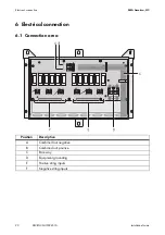
6.1 Connection area

Position

Description

A

Combined out negative

B

Combined out positive

C

Raceway

D

Equipment grounding

E

Positive string inputs

F

Negative string inputs

Summary of Contents for SBCBTL6

Page 1: ...SBCBTLUS IUS094510 IMUS SBCBTLUS Version 1 0 US Sunny Boy Accessories SUNNY BOY COMBINER BOX TLUS SBCBTL6 Installation Guide...

Page 2: ......

Page 3: ...cumstances The exclusion of implied warranties may not apply in all cases under some statutes and thus the above exclusion may not apply Specifications are subject to change without notice Every attem...

Page 4: ...unny Boy Combiner Box you must carefully read and follow all instructions cautions and warnings in this installation guide Warnings in this document A warning describes a hazard to equipment or person...

Page 5: ...uct works with high voltages All work on the product must be done as described in it s documentation Electric arc hazards The product has large electrical potential differences between its conductors...

Page 6: ...mbiner Box contains no user serviceable parts For all repair and maintenance always return the unit to an authorized SMA Service Center Before installing or using the Sunny Boy Combiner Box read all o...

Page 7: ...2 3 2 Scope of delivery 12 3 3 Identifying the Sunny Boy Combiner Box 13 4 Mounting 14 4 1 Safety 14 4 2 Selecting the mounting location 15 4 2 1 Conditions for installation 15 4 2 2 Dimensions 16 4 3...

Page 8: ...4 3 Connecting the positive strings 24 6 5 Connecting the inverter 25 6 5 1 Connecting DC 25 6 5 2 Connecting DC 26 7 Commissioning 26 8 Opening and closing 27 8 1 Opening the Sunny Boy Combiner Box...

Page 9: ...ed skills and knowledge in the construction and operation of the device Qualified personnel are trained to deal with the dangers and hazards involved in installing electric devices 1 2 Validity This m...

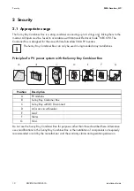
Page 10: ...Principle of a PV power system with the Sunny Boy Combiner Box Do not use the Sunny Boy Combiner Box for purposes other than those described here Alternative uses modifications to the Sunny Boy Combi...

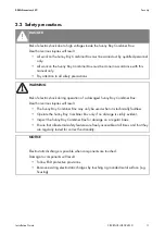
Page 11: ...ng operation of a damaged Sunny Boy Combiner Box Death or serious injuries will result The Sunny Boy Combiner Box may only be used when it is technically faultless Operate the Sunny Boy Combiner Box o...

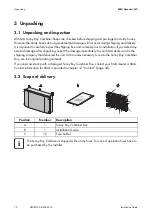
Page 12: ...mage after unpacking report the damage immediately to your SMA dealer and to the shipping company that delivered the unit If it becomes necessary to return the Sunny Boy Combiner Box use the original...

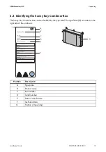
Page 13: ...nny Boy Combiner Box The Sunny Boy Combiner Box can be identified by the type label The type label G is located on the right side of the enclosure Position Description A Type plate B Product name C It...

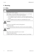
Page 14: ...ammable construction material Do not install the Sunny Boy Combiner Box in areas where highly flammable material is stored Do not install the Sunny Boy Combiner Box in potentially explosive areas WARN...

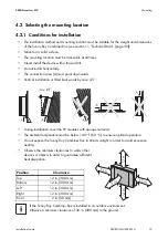
Page 15: ...rea A must point downwards Vertical installation or tilted backwards by max 45 During installation cover the PV modules with opaque material The ambient temperature must be below 140 F 60 C to ensure...

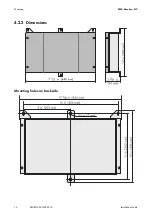
Page 16: ...Mounting SMA America LLC 16 SBCBTLUS IUS094510 Installation Guide 4 2 2 Dimensions Mounting holes on backside...

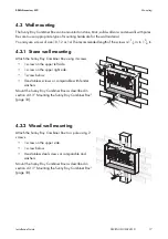
Page 17: ...ing Attach the Sunny Boy Combiner Box using 3 screws 1 screw on the upper left side 1 screw on the upper right side 1 screw below Use stainless screws or comparable with fender washers Mount the Sunny...

Page 18: ...Sunny Boy Combiner Box on the wall Align the mounting holes with the drilled holes 6 Insert the screws through the mounting holes of the Sunny Boy Combiner Box Tighten the screws clockwise 7 Ensure t...

Page 19: ...ngs into the knockout holes 5 Pull the cable conduits into the fittings and tighten them 6 Draw the string cables through the cable conduits into the Sunny Boy Combiner Box The cables are inserted int...

Page 20: ...20 SBCBTLUS IUS094510 Installation Guide 6 Electrical connection 6 1 Connection area Position Description A Combined out negative B Combined out positive C Raceway D Equipment grounding E Positive st...

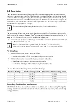
Page 21: ...size of PV string fuses calculate 1 56 x Isc of the PV module and round up to the next standard fuse size PV string fuses 1 Determine the required number and type of fuses Use the same number of fuse...

Page 22: ...erminals AC equipment grounding DC equipment grounding 1 terminal of the block remains unused Consider the required cable sizes and torques Refer to 11 1 Cable requirements page 33 1 Strip the cable b...

Page 23: ...pen the Sunny Boy Combiner Box as described in section 8 1 Opening the Sunny Boy Combiner Box page 27 2 Insert fuses into the fuse holders 3 Insert all fuse holders provided with the Sunny Boy Combine...

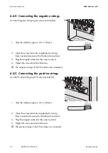
Page 24: ...Plug the stripped cable into the screw terminal 4 Tighten the screw terminal clockwise The negative strings of the PV modules are connected 6 4 3 Connecting the positive strings Use the Positive Strin...

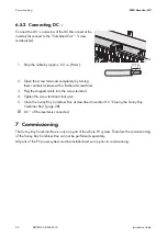
Page 25: ...able sizes and torques Refer to 11 1 Cable requirements page 33 6 5 1 Connecting DC Connect the DC conductors of the DC inverter disconnect at the inverter to the Combined Out screw terminals A 1 Stri...

Page 26: ...with a flat head screwdriver 3 Plug the stripped cable into the screw terminal 4 Tighten the screw terminal clockwise 5 Close the Sunny Boy Combiner Box as described in section 8 2 Closing the Sunny...

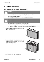
Page 27: ...are connecting wires and cables to the Sunny Boy Combiner Box The Sunny Boy Combiner Box is opened DANGER Risk of electric shock when opening the Sunny Boy Combiner Box under load Death or serious inj...

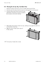
Page 28: ...e lid to ensure it is undamaged and in correct position 3 Carefully position the lid on the front of the Sunny Boy Combiner Box Ensure that no pressure is exerted on the connections when the lid is at...

Page 29: ...life due to high voltages on exposed contacts All fuse holders must be plugged in even if the fuse holder is blank DANGER Danger to life due to high voltages within the device Do not touch power cable...

Page 30: ...ll the fuses out of the fuse holders 4 Insert the new fuses into the fuse holders 5 Insert all fuse holders provided with the Sunny Boy Combiner Box 6 Close the Sunny Boy Combiner Box as described in...

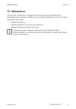
Page 31: ...will help to ensure long life and high efficiency of your PV system Maintenance may include Inspection of mounting Inspection of electrical connections and components Cleaning of housing and interior...

Page 32: ...rrent per string 20 A Nominal DC output current 36 A Maximum DC output current 56 16 A Maximum number of strings 6 Maximum number of fuses 12 Dimensons W x H x D 17 2 in x 12 1 in x 3 8 in 437 mm x 30...

Page 33: ...Combiner Box Sunny Boy Combiner Box and Sunny Boy Connection Sunny Boy Combiner Box The conductor cross section must be adjusted to the maximum current The listed terminals are rated to a temperature...

Page 34: ...erter if applicable Type and number of modules connected if applicable Communication method where necessary Serial number of the Sunny Boy Combiner Box Sunny Boy failure or warning number Display mess...

Page 35: ......

Page 36: ...4 NFSJDB XXX 4 NFSJDB DPN...

Reviews: