background image

SMA Solar Technology AG

6  Installation

Operating Manual

MC_BOX_36-BE-en-20

19

Requirement:

When using a crane with hoist, the four lifting lugs must be attached (see Section 6.3.2, 

page 17).

Additionally required mounting material (not included in the scope of delivery):

Four suitable screws to attach the Multicluster Box

Procedure:

1. Remove all fastening screws from the kick plates at the front and rear. Use a wrench with a 

TX 30 attachment.

2. Remove the kick plates and set them aside.

3. Retain the kick plates and the fastening screws for later use.
4. When using a forklift truck or pallet truck, slide the fork underneath the Multicluster Box and 

transport the Multicluster Box to the mounting location.

5. When using a crane with fork, slide the crane fork underneath the Multicluster Box and transport 

the Multicluster Box to the mounting location.

6. When using a crane with hoist, proceed as follows to transport the Multicluster Box:

– Attach the hoist to all four lifting lugs on the Multicluster Box.
– Raise the crane hook slowly until the hoist is taut.
– Ensure that the hoist is attached correctly.
– Raise the Multicluster Box and transport to the mounting location.

7. Attach the Multicluster Box to the foundation using four suitable screws.

Damage to the Multicluster Box due to inappropriate transport

If the Multicluster Box is set down on uneven surfaces, it may cause buckling so that the doors will 

no longer close properly. This can lead to moisture and dust penetrating the Multicluster Box.

Α Never place the Multicluster Box on a non-reinforced, uneven surface.
Α Never transport the Multicluster Box with mounted kick plates.

Summary of Contents for MULTICLUSTER BOX 36

Page 1: ...MC_BOX_36 BE en 20 Version 2 0 ENGLISH Operating Manual MULTICLUSTER BOX 36...

Page 2: ...ur device These are also available online at www SMA Solar com and can be downloaded and are available on paper from the usual sales channels if required Trademarks All trademarks are recognized even...

Page 3: ...ion 14 6 2 Preparing the Mounting Location 16 6 3 Transport 17 6 3 1 Transport Options 17 6 3 2 Attaching the Lifting Lugs 17 6 3 3 Transporting and Mounting the Multicluster Box 18 7 Electrical Conne...

Page 4: ...zard Protection Cover 35 7 12 Protecting the Door Seals from Freezing 35 7 13 Mounting the Kick Plates 35 8 Commissioning the Multicluster Box 36 9 Disconnecting the Multicluster System from Voltage S...

Page 5: ...in the documentation of the Sunny Island 5048 6 0H 8 0H Symbols Nomenclature Symbol Explanation Indicates a hazardous situation which if not avoided will result in death or serious injury Indicates a...

Page 6: ...g Manual Abbreviations Abbreviation Designation Explanation AC Alternating Current DC Direct Current EMC Electromagnetic Compatibility MSL Mean Sea Level PV Photovoltaics SOC State of Charge State of...

Page 7: ...Box is a main AC distribution board to which you can connect up to twelve three phase clusters Each cluster consists of three Sunny Island inverters of the same device type with parallel DC side conne...

Page 8: ...rference in accordance with the locally applicable standards and directives For safety reasons it is not permitted to modify the product or install components that are not explicitly recommended or di...

Page 9: ...all times Danger to life due to electric shock High voltages are present in the Multicluster Box Touching live components results in death or serious injury due to electric shock Disconnect the Multic...

Page 10: ...incomplete or damaged Figure 2 Components included in the scope of delivery Object Number Description A 1 Multicluster Box B 1 Switch cabinet key C 4 Lifting lug D 1 Data cable 10 m black E 3 Control...

Page 11: ...n and cable laying material For connecting the generator PV plant and loads Distribution board with protection units 2 One distribution board each for the PV plant and the loads LV HRC fuse link as re...

Page 12: ...ard for the Sunny Island inverters one generator and one PV plant Load shedding Automatic bypass for the generator Active anti islanding Reverse current monitoring 5 2 Type Label The type label clearl...

Page 13: ...Allow the product to cool down sufficiently before carrying out any work Wear personal protective equipment such as safety gloves Observe the documentation Observe all documentation that is supplied w...

Page 14: ...L For altitudes over 2 000 m above MSL contact the SMA Service Line Danger to life due to fire or explosion Despite careful construction electronic devices can cause fires if they are not installed pr...

Page 15: ...hnology AG 6 Installation Operating Manual MC_BOX_36 BE en 20 15 Observe minimum clearances Figure 3 Minimum clearances Observe the permitted mounting position Figure 4 Permitted and prohibited mounti...

Page 16: ...ments and dimensions of the drill holes Additionally required mounting material not included in the scope of delivery Four suitable screw anchors to fasten the Multicluster Box Procedure 1 On the moun...

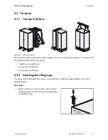
Page 17: ...ns of transport to lift the Multicluster Box off the Euro pallet Forklift truck or pallet truck Crane with suitable fork Crane with suitable hoist 6 3 2 Attaching the Lifting Lugs To transport the Mul...

Page 18: ...transporting the Multicluster Box always keep it as close to the ground as possible Use means of transportation which are adequate for the weight of the Multicluster Box max 400 kg Transport the Mult...

Page 19: ...ng a crane with fork slide the crane fork underneath the Multicluster Box and transport the Multicluster Box to the mounting location 6 When using a crane with hoist proceed as follows to transport th...

Page 20: ...A Fuse switch MC F1 Generator for connecting the line conductors of the generator B Busbar MC X1 for connecting the neutral conductor of the generator C Busbar MC X2 for connecting the neutral conduct...

Page 21: ...ables and the data cable I Circuit breakers for the Sunny Island inverters K Connection area for connecting the Sunny Island power cables Object Description A Double membrane seal for the connection c...

Page 22: ...g the Multicluster Box 1 Unlock the Multicluster Box with the switch cabinet key supplied 2 Open the right hand door until the door stopper clicks into place 3 Release the left hand door with the turn...

Page 23: ...crews with washers from the contact hazard protection cover and remove the cover Use a TX 30 screwdriver 2 Set the contact hazard protection cover pan head screws and washers aside for later use Posit...

Page 24: ...generator the PV plant or the loads press an M12 terminal lug onto the cable 7 Label each Sunny Island connection cable using the adhesive web included in the delivery 8 Reinsert the double membrane...

Page 25: ...ands lift the fuse holder up and out of the anchorage 6 Release the screws on the cover of the terminals and remove the cover Use a PH 2 screwdriver 7 Connect the line conductors L1 L2 and L3 to the f...

Page 26: ...ad grounding busbar terminal lug fender washer spring washer nut 14 Connect the neutral conductor to the busbar MC X1 AF 19 torque 25 Nm Make sure to adhere to the following screw assembly screw head...

Page 27: ...installation conditions determine the required fuse link for the fuse switch Observe the following requirements Permitted fuse rating 100 A to 500 A The currents of the Sunny Island the PV plant and...

Page 28: ...switch terminal 7 Ensure that there is a right hand rotating magnetic field at the load connection point 8 Insert the terminal cover and tighten the screws PH 2 screwdriver torque 4 Nm 9 Insert the f...

Page 29: ...unprotected connection cable between the Multicluster Box and PV main distribution board When planning the short circuit protection of cables the PV inverter and Sunny Island inverters may be disrega...

Page 30: ...rminal of neutral conductor terminal lug fender washer spring washer nut 3 Connect the neutral conductor and the line conductors to the busbars MC X3 PV System according to the labels AF 19 torque 25...

Page 31: ...circuit breakers for the Sunny Island inverters The higher the temperature the earlier the circuit breakers will trip At high ambient temperatures the derating function of the Sunny Island inverters...

Page 32: ...ter Connect slave 2 to the terminals Main Cluster Slave 2 as follows Connect the line conductor to the terminal 7 L1 Connect the neutral conductor to the terminal 8 N Connect the grounding conductor t...

Page 33: ...tension at the terminals 7 Reinsert the cover of the Sunny Island connection area 8 Insert the four screws into the cover of the Sunny Island connection area and fasten them hand tight 7 9 Grounding t...

Page 34: ...a black data cable Procedure 1 Remove one cable support sleeve from the cable entry in the bottom of the Multicluster Box 2 Insert the three red control and measuring cables and the black data cable...

Page 35: ...he contact hazard protection cover in front of the rear panel of the Multicluster Box 2 Ensure that the attachment points on the contact hazard protection cover are correctly aligned 3 Attach the cont...

Page 36: ...ontact must be installed The kick plates on the base of the Multicluster Box must be attached Procedure 1 Close the Multicluster Box Slightly raise the door stopper of the left hand door with your foo...

Page 37: ...inst reconnection 5 Shut down the generator and secure against reconnection 6 Open the Multicluster Box 7 In the Multicluster Box open all Sunny Island circuit breakers 9 Remove the contact hazard pro...

Page 38: ...Busbars and terminals in the Multicluster Box can get hot during operation Do not touch busbars or terminals Maintenance work Recommended maintenance interval Check the inside of the Multicluster Box...

Page 39: ...instructions of the paint manufacturer Use touch up paint or alternatively 2K PUR acrylic paint to repair extensive surface damage Observe the relevant instructions of the paint manufacturer 12 months...

Page 40: ...eattach the kick plates to the Multicluster Box 11 2 Storing the Multicluster Box Store the Multicluster Box in a dry place where the ambient temperature is between 25 C and 60 C 11 3 Disposing of the...

Page 41: ...y range 40 Hz to 70 Hz Current at rated values 3 x 435 A Diameter of the screws for cable connection 12 mm Torque 25 Nm Maximum connectable conductor cross section 300 mm Fuse LV HRC size 3 Permissibl...

Page 42: ...ction 12 mm Torque 25 Nm Maximum connectable conductor cross section 300 mm Fuse LV HRC size 3 Permissible fuse rating 100 A to 500 A Number 1 x three phase PV rated power 360 kW AC current at rated v...

Page 43: ...tive cover in accordance with IEC 60529 IP20 Protection class in accordance with IEC 417 II Overvoltage category in accordance with EN 60664 Overvoltage category 3 Rated impulse withstand voltage at 2...

Page 44: ...MA Australia Pty Ltd Sydney Toll free for Australia 1800 SMA AUS 1800 762 287 International 61 2 9491 4200 Belgien Belgique Belgi SMA Benelux BVBA SPRL Mechelen 32 15 286 730 Brasil Vide Espa a Espanh...

Page 45: ...rg Siehe Belgien Voir Belgique Magyarorsz g l sd esko Csehorsz g Nederland zie Belgien Belgi sterreich Siehe Deutschland Per Ver Espa a Polska Patrz esko Czechy Portugal SMA Solar Technology Portugal...

Page 46: ...d Co Ltd 66 2 670 6999 SMA Technology Korea Co Ltd 82 2 508 8599 SMA Beijing Commercial Company Ltd 86 10 5670 1350 SMA Japan K K 81 3 3451 9530 971 2 698 5080 SMA Middle East LLC Other countries Inte...

Page 47: ......

Page 48: ...www SMA Solar com SMA Solar Technology...

Reviews: