' SLS loudspeakers Inc., 2002. All rights reserved.
6
The RLA 1 high frequency section has two coupled PRD1000 ribbon drivers which
directly radiate sound with a planar coherent wavefront, ideally conforming to the
requirements of the line source concept.
In addition to superior wavefront generation, the RLA 1 has a unique but simple design
solution for reproducing midrange and high frequency signals with the highest degree of
coherency. It is extremely important for producing even horizontal dispersion, to have a
symmetrical driver arrangement with sections having coincident axes of symmetry. This
leads to the HF section being positioned between midrange drivers. On the other hand,
the midrange drivers must be mounted very closely to each other to prevent the system
from having narrow horizontal dispersion (beaming) at upper midrange crossover point
(typically around 1-1.5 kHz). If a system is beaming in this most critical vocal range, the
entire performance will be severely compromised. Line array application techniques
require at least 90
°
nominal horizontal dispersion (at –6 dB) in order to maintain
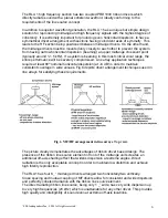
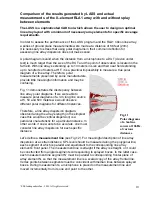
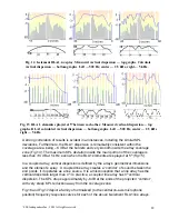
consistent coverage in wide venues. Fig.6 depicts driver arrangement techniques used in
line arrays for satisfying these requirements.
The picture clearly demonstrates the advantages of ribbon driver based design. The
presence of the ribbon line source element in front of the midrange units creates an
additional off-axis shading effect that widens dispersion at extreme angles. Direct
radiation is the only acceptable concept in order to maintain low distortion and achieve
high fidelity reproduction.
The RLA1 has four 6 _” midrange drivers arranged two horizontally/two vertically.
Close spacing and mutual coupling of MF drivers allow for consistent and wide dispersion
and perfectly coherent radiation with the ribbon line source element.
The direct radiating ribbon line source, being only 1 _” wide, has very wide dispersion up
to very high frequencies (20 kHz) which is unattainable for any other driver. This provides
high quality and intelligibility of sound even at extreme off-axis locations.
Fig.6 MF/HF arrangement in line arrays. Top view.


