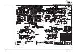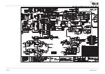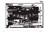
Issue 8 Page 233 of 286
17.1 Service Information
17.1.1 SI 990301
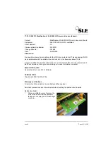
Calibration of Issue 2 of the A0745 Pressure Drift Board
Introduction
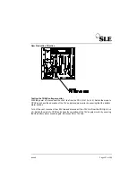
Issue 2 of the Pressure Drift Board (both A0745/01 and A0745/02 ) incorporates an extra
adjustment (RV3) and has a different calibration procedure to issue 1 which only has 2 adjust-
ments. The extra adjustment was introduced because in a small number of cases it was found
that the gain of the pressure transducers varied between samples to such an extent that trans-
ducers could not be matched by offset adjustment alone (over the complete range of the trans-
ducer).
Calibration procedure for the SLE2000HFO.
A0745 board issue 2 (recognisable as having three potentiometers)
a)
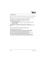
Whilst monitoring the DC voltage at DIFF, vary the pressure to the proximal airway port
over the complete range (60 to -60cmH2O).
Adjust RV3 until the voltage measured at DIFF is the same at +60cmH
2
O as it is at -60cmH
2
O
to within 20mV. (DIFF should be in the region of 8V).
Pay special attention to the indicated polarities when measuring voltages.
b)
Set the DC voltage between HIGH(+) and LOW(-) to +180mV ±5mV using
RV2
.
c)
Set the DC voltage between HIGH(+) and DIFF(-) to +90mV ±5mV using
RV1
.
d)
Repeat steps b) and c) until both voltages are correct to within ±5mV.
Verify that the voltage between DIFF(+) and LOW(-) is +90mV±5mV.
Calibration procedure for the SLE2000HFO ‘PLUS’.
A0745 board issue 2 (recognisable as having three potentiometers)
a)
Whilst monitoring the DC voltage at DIFF, vary the pressure to the proximal airway port
over the complete range (140 to -70cmH2O).
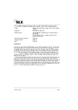
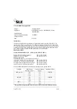
Subject
:Calibration of Issue 2 of the A0745 Pressure Drift Board
Equipment
:SLE2000 HFO and SLE2000 HFO ‘PLUS’ Infant
Ventilators
Serial Numbers
:Boards A0745 issue 2 (recognisable as having 3
potentiometers instead of 2)
Service Information Number
:Si 990301
Change Note Ref
:CN 0625
Date
:02/03/99
Summary of Contents for 2000 HFO+
Page 1: ...Issue 8 SLE 2000 HFO Ventilator Service manual High Frequency Oscillatory Ventilator ...
Page 8: ...Page 8 of 286 Issue 8 This page is intentionally blank ...
Page 9: ...Issue 8 Page 9 of 286 Introduction ...
Page 11: ...Issue 8 Page 11 of 286 Ventilator Control Description ...
Page 20: ...Page 20 of 286 Issue 8 This page is intentionally blank ...
Page 21: ...Issue 8 Page 21 of 286 Access to Internal Components ...
Page 34: ...Page 34 of 286 Issue 8 This page is intentionally blank ...
Page 35: ...Issue 8 Page 35 of 286 Maintenance ...
Page 43: ...Issue 8 Page 43 of 286 Overhual ...
Page 45: ...Issue 8 Page 45 of 286 Exchanging a Pneumatic Unit ...
Page 47: ...Issue 8 Page 47 of 286 Setup and Calibration ...
Page 74: ...Page 74 of 286 Issue 8 This page is intentionally blank ...
Page 75: ...Issue 8 Page 75 of 286 Troubleshooting Chart ...
Page 80: ...Page 80 of 286 Issue 8 This page is intentionally blank ...
Page 81: ...Issue 8 Page 81 of 286 Technical Specification ...
Page 98: ...Page 98 of 286 Issue 8 This page is intentionally blank ...
Page 99: ...Issue 8 Page 99 of 286 Circuit Details ...
Page 100: ...Page 100 of 286 Issue 8 15 Circuit Details 15 1 A0700 03 Display Board Assembly ...
Page 101: ...Issue 8 Page 101 of 286 15 1 1 CD A0700 03 Display Board Circuit Diagram ...
Page 103: ...Issue 8 Page 103 of 286 15 2 A0701 02 LED PCB Assembly ...
Page 104: ...Page 104 of 286 Issue 8 15 2 1 CD A0701 02 LED Board Circuit Diagram ...
Page 107: ...Issue 8 Page 107 of 286 15 3 AS A0702 05 CPU PCB Issue 2 Sheet 1 of 2 ...
Page 108: ...Page 108 of 286 Issue 8 15 3 1 AS A0702 05 Issue 2 Sheet 2 of 2 ...
Page 114: ...Page 114 of 286 Issue 8 15 4 AS A0702 05 CPU PCB Issue 3 Sheet 1 of 2 ...
Page 115: ...Issue 8 Page 115 of 286 15 4 1 AS A0702 05 CPU PCB Sheet 2 of 2 ...
Page 121: ...Issue 8 Page 121 of 286 15 5 AS A0702 05 CPU PCB Issue 3 Sheet 1 of 2 See detail A ...
Page 122: ...Page 122 of 286 Issue 8 15 5 1 Ventilator CPU Board Detail A C0481 R0658 Link Cut track ...
Page 129: ...Issue 8 Page 129 of 286 15 6 AS A0736 04 Main PCB Revision E Issue 1 ...
Page 150: ...Page 150 of 286 Issue 8 15 10 AS A0739 02 Motor Drive PCB Issue 1 Sheet 1 Revision B ...
Page 151: ...Issue 8 Page 151 of 286 15 10 1 AS A0739 02 Motor Drive PCB Issue 1 Sheet 2 Revision B ...
Page 155: ...Issue 8 Page 155 of 286 15 11 AS A0739 02 Motor Drive PCB Issue 2 Revision C ...
Page 159: ...Issue 8 Page 159 of 286 15 12 AS A0756 HFO Start up Motor PCB Issue 1 ...
Page 161: ...Issue 8 Page 161 of 286 15 13 AS A0738 02 Alarm PCB Assembly ...
Page 162: ...Page 162 of 286 Issue 8 15 13 1 CD A0738 02 Alarm PCB Circuit Diagram ...
Page 165: ...Issue 8 Page 165 of 286 15 14 A0745 01 Pressure Drift Monitor Board ...
Page 166: ...Page 166 of 286 Issue 8 15 14 1 CD A0745 Pressure Drift Board Circuit Diagram ...
Page 168: ...Page 168 of 286 Issue 8 15 15 A0746 Flow Trigger PCB ...
Page 174: ...Page 174 of 286 Issue 8 15 19 Front Panel ...
Page 175: ...Issue 8 Page 175 of 286 15 20 SK0057 Power Supply Wiring Diagram ...
Page 176: ...Page 176 of 286 Issue 8 15 21 CD W0307 Electronic Pneumatic Module interconnection ...
Page 177: ...Issue 8 Page 177 of 286 15 22 Electronic Chassis S RZ 2000 HFO ...
Page 178: ...Page 178 of 286 Issue 8 ...
Page 209: ...Issue 8 Page 209 of 286 16 A3 Circuit Diagram Appendix A3 circuit Diagram Appendix ...
Page 210: ...Page 210 of 286 Issue 8 This page is intentionally blank ...
Page 211: ...Issue 8 Page 211 of 286 CD A0702 05 Issue 2 ...
Page 212: ...Page 212 of 284 ...
Page 213: ...Issue 8 Page 213 of 286 CD A0702 05 Issue 3 ...
Page 214: ...Page 214 of 284 ...
Page 215: ...Issue 8 Page 215 of 286 CD A0702 05 Issue 4 ...
Page 216: ...Page 216 of 284 ...
Page 218: ...Page 218 of 284 ...
Page 220: ...Page 220 of 284 ...
Page 222: ...Page 222 of 284 ...
Page 224: ...Page 224 of 284 ...
Page 225: ...Issue 8 Page 225 of 286 CD W0317 Issue 2 Wireloom Diagram ...
Page 226: ...Page 226 of 284 ...
Page 227: ...Issue 8 Page 227 of 286 CD W0317 Issue 3 Wireloom Diagram ...
Page 228: ...Page 228 of 284 ...
Page 229: ...Issue 8 Page 229 of 286 CD W0317 Issue 4 Wireloom Diagram ...
Page 230: ...Page 230 of 284 ...
Page 231: ...Issue 8 Page 231 of 286 Service Information and Technical Bulletins ...
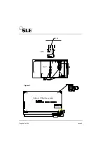
Page 240: ...Page 240 of 286 Issue 8 Figure 1 Figure 2 U14 U18 U7 Solder to PCB at these points Figure 3 ...
Page 241: ...Issue 8 Page 241 of 286 Figure 4b ...
Page 247: ...Issue 8 Page 247 of 286 100nf ...
Page 262: ...Page 262 of 286 Issue 8 Pneumatic Schematic ...
Page 284: ...Page 284 of 286 Issue 8 This page is intentionally blank ...
Page 286: ......


