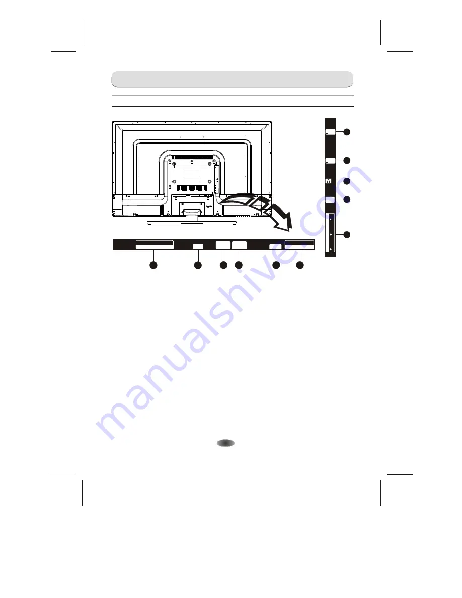
EXTERNAL SCHEMATIC AND INSTALLATION
Back Panel
Note
: The graphics are for representation only.
-7-
1
2
3
4
5
7
1
8
1
9
1.
HDMI1/HDMI2/HDMI3:
Connect HDMI input signal from signal source such as DVD.
2. PC IN:
Connect a PC via a VGA cable.
3. PC AUDIO IN:
Audio input for PC and Audio input for HDMI when the signal is DVI timing.
4. ANTENNA IN:
Connect a coaxial cable to receive signal from the antenna or cable.
5. S/PDIF:
Use a 75 ohm coaxial cable to connect your TV to a compatible audio receiver. You
can use the S/PDIF interface as digital audio output,in order to achieve better sound quality.
6. AUDIO IN:
Connect AUDIO input signal from signal source such as DVD.
7. COMPONENT(Y/VIDEO Pb Pr IN):
Connect COMPONENT signal from signal source
such as DVD. VIDEO share the same port with Y port.
8. EARPHONE:
Audio output, speakers will be muted when earphone is plugged in and the
headphone is selected; speaker will be not muted when an audio output plug
is inserted and line output in the menu is selected. The output audio signal is
needed when TV connects to other audio instruments, such as an audio
amplifier. You can use the EARPHONE interface as anolog audio output in
order to achieve better sound quality.
9. USB1/USB2:
USB port.
6
1
9
PC IN
PC
AUDIO IN
S/PDIF
HDMI IN
HDMI3
HDMI2
ANTENNA
IN
AUDIO IN
LEFT
RIGHT
USB1
5V 500mA
HDMI1
IN
USB2
5V 500mA
C
O
M
P
O
N
E
N
T
P
b
Y
/V
ID
E
O
P
r
200MM
100MM
Summary of Contents for 39e36
Page 1: ......


