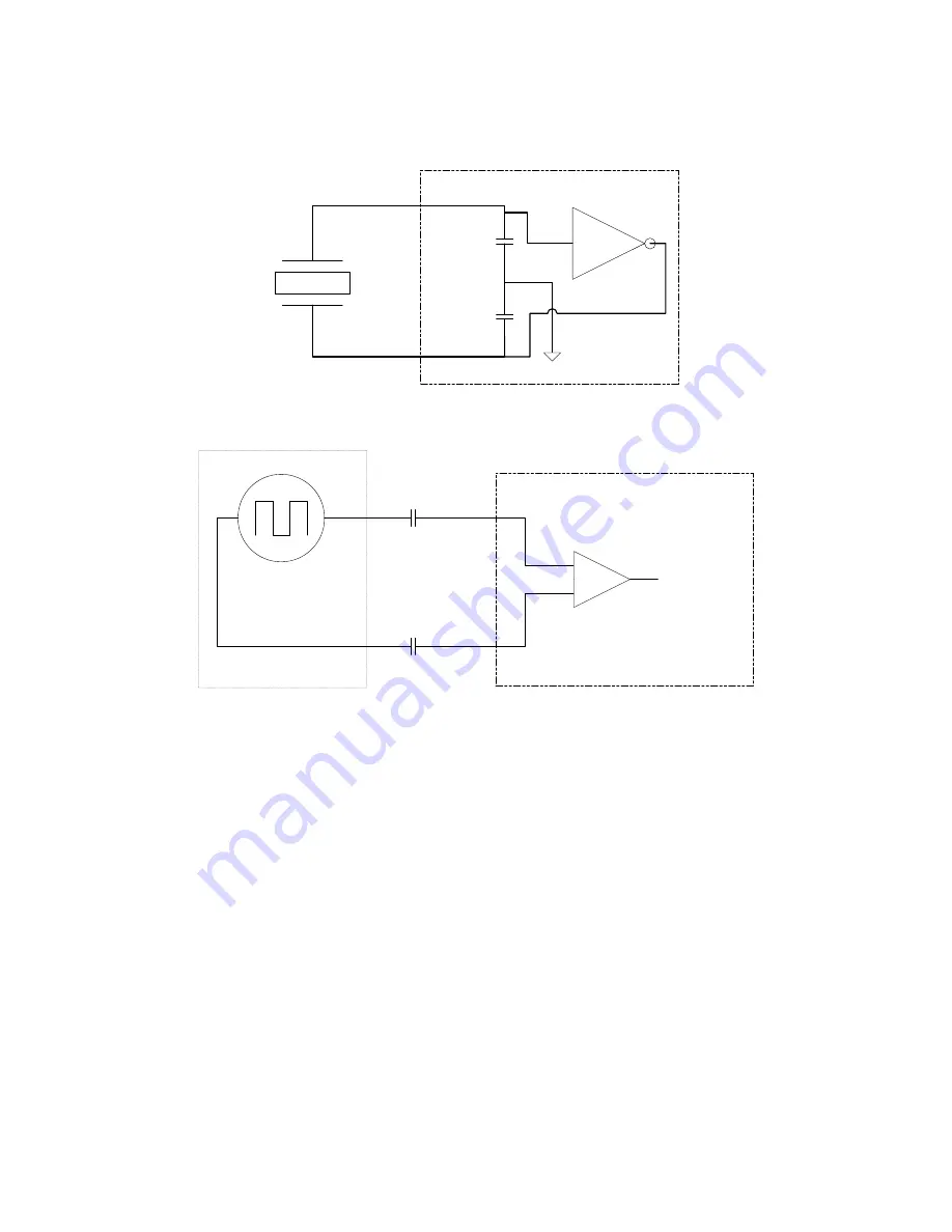
3.1 Input Clock Terminations
The crystal oscillator supports 16-50 MHz crystals and supports internal crystal loads. When external input clocks can only be AC-cou-
pled into the XA/XB input. The CLKIN_x/CLKIN_x# can accept either a DC-coupled CMOS input clock or AC-coupled CMOS/differential
clocks. The recommended terminations are shown in the figures below.
XA
XB
Clock IC
Figure 3.1. Termination for Connecting a Crystal to XA/XB Pins in "Crystal" Mode
XA
XB
Clock IC
External oscillator/clock source
0.1 µF
0.1 µF
Input buffer
Limit swing at the input to
less than 1V
Add any output termination
needed by the external
oscillator/clock source
before the 0.1 µF
capacitances
Figure 3.2. Termination for Connecting an External Clock Input to XA/XB Pins
Key differences between
Figure 3.1 Termination for Connecting a Crystal to XA/XB Pins in "Crystal" Mode on page 6
3.2 Termination for Connecting an External Clock Input to XA/XB Pins on page 6
1. Termination for a reference clock input on XA/XB must be external to Si5357.
2. The choice to enable the internal crystal oscillator or internal capacitance loads or to disable their use is controlled by programming
the Si5357 by setting the right user registers (refer to the in this reference manual or to the
).
Because of the above differences, it is not possible to use these two modes interchangeably without modifications to terminations and
internal register re-programming of the Si5357.
Si5357 Reference Manual • Input Clocks
Skyworks Solutions, Inc. • Phone [781] 376-3000 • Fax [781] 376-3100 • [email protected] • www.skyworksinc.com
6
Rev. 0.2 • Skyworks Proprietary Information • Products and Product Information are Subject to Change Without Notice • July 26, 2021
6


