background image

SKY899 

Installation Manual 


Page 3-2 - Installation Checkout 

009-11900-001 

July 18, 2013 


Revision F 

3.2  CONTROLS 

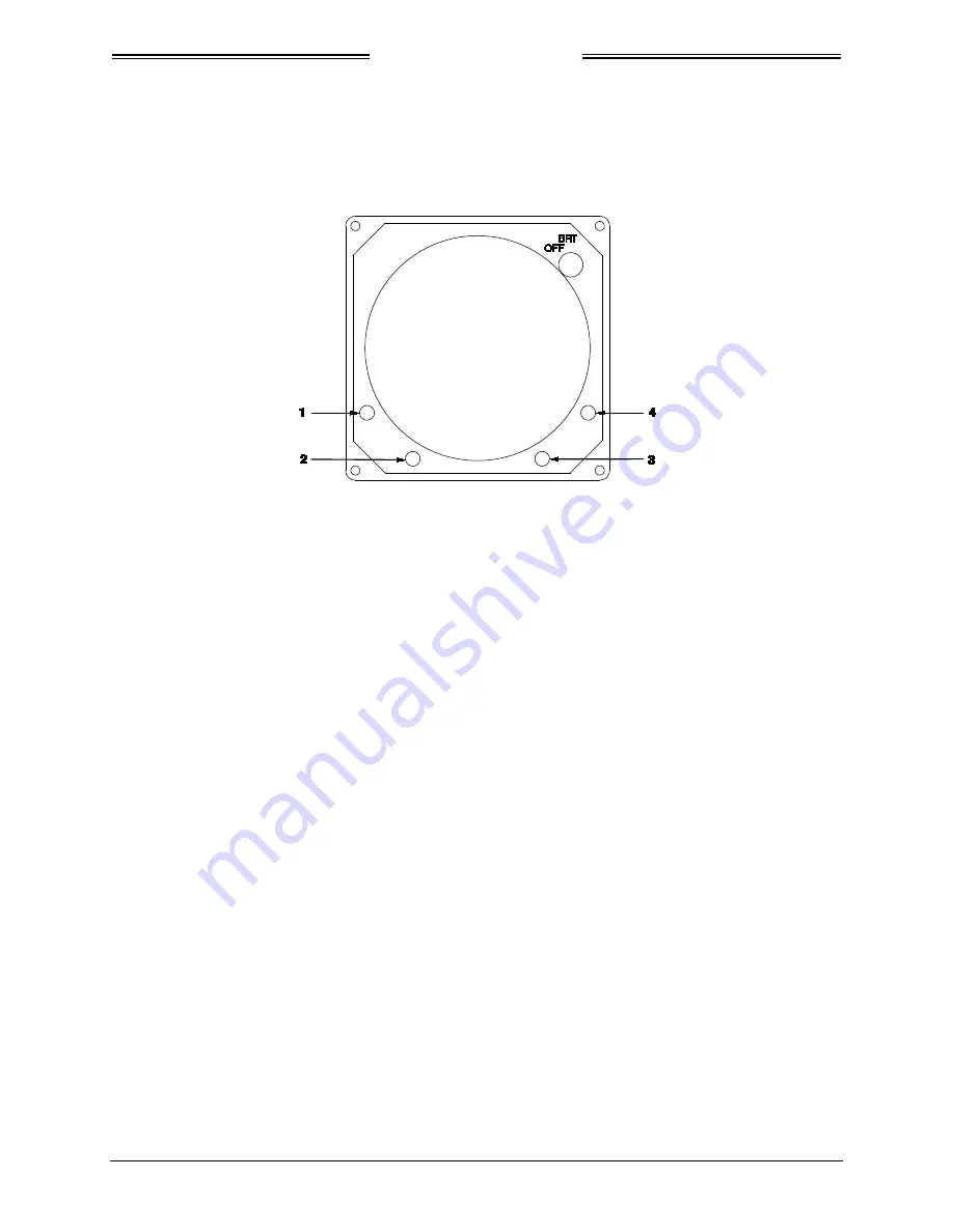
All operating controls are located on the front of the display. Figure 3-1 shows the locations of the 
controls. Complete operating instructions are provided in the SKY899 Pilot's Guide supplied with each 
system. 


Figure 3-1: Controls 

OFF/BRT 

Switch 

Power is applied by rotating the knob clockwise past the detent. Continued clockwise 
rotation increases display brightness. 

1, 2, 3, & 4 

Pushbuttons 

Also referred to as soft-keys (1), (2), (3), and (4). In every operating mode a label 
identifying the button function will be displayed next to the button.  

3.3  CHECKOUT PROCEDURE 

The TT391 Flightline Tester simulates both a ground based secondary surveillance radar (SSR) and an 
airborne transponder. With the SKY899 set to GROUND TEST (i.e., the barometric altimeter is simulated 
to 50,000 ft, heading simulated to 0 degrees, and the radar altimeter simulated to 2,500 ft) the TT391 will 
simulate two targets; a Traffic Advisory (i.e., a solid circle) at ¼ nm and Other Traffic (i.e., open 
diamond) at 4.5 nm. Both targets will be displayed in level flight at own aircraft altitude (i.e., "00" 
displayed above the traffic symbol). 

If the indications given in the following procedure, except for the Flightline Tester, are not obtained, refer 
to the troubleshooting procedures in Chapter 4. If indications given for the Flightline Tester are not 
obtained, refer to the maintenance section of the TT391 Instruction Manual. 

Make sure the aircraft's transponder is in the STBY mode and the DME is turned OFF. Verify all avionics 
equipment interfaced with the SKY899 (i.e., GPS, ADC, AHRS, synchro compass, encoding altimeter) is 
turned ON and signal condition is valid. 

NOTE 

After power up, it may take a couple of minutes for the altitude encoder to 
return a valid altitude to the transponder and SKY899. 

1.


Turn SKY899 ON. The display will show a start-up screen similar to one shown in Figure 3-2. After 
start-up screen appears, rotate the OFF/BRT switch. Verify that clockwise rotation increases display 
brightness. 


The document reference is online, please check the correspondence between the online documentation and the printed version.

Summary of Contents for SKY899

Page 1: ... 2 All test equipment used in completing these tests shall be calibrated in accordance with the manufacturer s recommendations 3 This section provides checkout information for the SKY899 using the WX 1000 Display If using an alternate display use Appendix F for installation checkout 4 Checkout of the WX 1000 processor should be done in accordance with the procedures detailed in the WX 1000 Install...

Page 2: ...a Traffic Advisory i e a solid circle at nm and Other Traffic i e open diamond at 4 5 nm Both targets will be displayed in level flight at own aircraft altitude i e 00 displayed above the traffic symbol If the indications given in the following procedure except for the Flightline Tester are not obtained refer to the troubleshooting procedures in Chapter 4 If indications given for the Flightline Te...

Page 3: ...ge Calibration will be done during system setup verification and operation Figure 3 3 Standby Screen 3 3 1 System Setup The system configuration can be done using the service menu or it can be downloaded with a previously saved configuration using the Compact Flash Card Both setup procedures are described below and assume familiarity with service menu operation see chapter 4 for operation informat...

Page 4: ...d at a comfortable level then select exit to return to setup menu 5 From the Setup menu select ARINC 429 ports and manually configure each receiver channel Refer to paragraph 4 4 1 4 NOTES 1 It is possible for multiple data inputs barometric altimeter radio altimeter magnetic heading and GPS navigation from one source to be received on one channel e g ARINC 429 superbus Multiple data inputs will b...

Page 5: ...eturn to Service Menu e The Save or Revert menu will appear upon exiting setup menu Select Save Changes to keep current configuration Selecting Revert to Old Settings will cause system to exit the service menu without saving changes 7 To verify changes made to the configuration module turn the SKY899 OFF and then enter the Service Menu see paragraph 4 4 and repeat Step 6 8 Perform system setup ver...

Page 6: ...h altitude and heading sensor Verify data monitors show the correct input changes i e sensing of these signals b If the information is not correct the sensor has failed to communicate with the TRC Check operation of the sensor and connections between the TRC and sensor c Select exit until you return to the Service Menu 4 From the Service Menu select Ground Test see paragraph 4 4 4 5 From the Groun...

Page 7: ... to sub step f If the Flightline Tester AC Converter Power Supply is to be utilized proceed to sub step d d Connect the AC Converter Power Supply cable connector to the chassis external connector e Connect the AC Converter Power Supply input power cable connector to one of the following AC sources 115 Vac 60 Hz 115 Vac 400 Hz f Set the Flightline Tester POWER switches to the ON position g Verify t...

Page 8: ...path distortion see step 1 3 During these tests the SKY899 may detect and display other active targets 4 To obtain a better line of sight it may be necessary to elevate the patch antenna d Set the TT391 POWER switch to the OFF Repeat procedure from each test point Step 15 can be done from the last test point NOTE To prevent SKYWATCH HP from tracking the movement of the test set it is necessary to ...

Page 9: ...are cleared from the aircraft s instruments 2 Turn SKY899 ON The display should show a start up screen similar to one shown in Figure 3 2 3 After approximately thirty seconds observe the STANDBY screen and then press the TEST button soft key 2 4 The display should present a screen similar to that shown in Figure 3 5 Figure 3 5 Self Test Screen 5 If the SKY899 passes the self test the system will r...

Page 10: ...be connected to P1 89 AUDIO_H 2 150 ohm audio systems should be connected to P1 90 AUDIO_L 3 Audio common is connected to P1 91 AUDIO_C NOTE Audio output from the TRC is transformer isolated 7 If SKY899 fails the self test a The SKY899 Failed screen with an error message indicating the type of failure will be displayed b The voice message SKYWATCH SYSTEM TEST FAILED will be enunciated over the coc...

Reviews: