background image

DC Electric Full-size RTs

December 2007

Page 25

TM

Section 2 - Operation 

Visual and Daily Maintenance Inspections

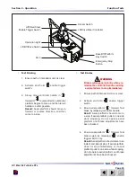
Electrical Panel

Hydraulic Pump/Motor 

Assembly

Main Manifold

Brake Manifold

Base Control 
Switches

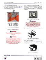
2.8-6  Hydraulic/Electrical Compartment

Ensure  all  compartment  latches  are  secure 

 -

and in proper working order.

Electrical Panel

• 

Ensure  panel  is  properly  secured  and 

 -

there is no visible damage.

Ensure  there  are  no  loose  wires  or 

 -

missing fasteners. 

Manifolds

• 

Ensure all fittings and hoses are properly 

 -

tightened  and  there  is  no  evidence  of 
hydraulic leakage.

Ensure  there  are  no  loose  wires  or 

 -

missing fasteners.

Tilt Sensor

• 

Ensure  tilt  sensor  is  properly 

 -

secure  and  there  is  no  visible 
damage.

Base Control Switches

• 

Ensure  there  are  no  signs  of  visible 

 -

damage  and  all  switches  are  in  their 
neutral positions.

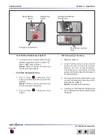
Emergency Lowering Access Rod

• 

Ensure rod is properly secured and there 

 -

is no visible damage.

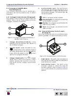
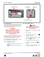
Tilt Sensor

Summary of Contents for SJ 8831E

Page 1: ...Operating Manual Rough Terrain 800E Series ANSI CSA MODELS SJ 8831E SJ 8841E 143867AB A September 2010...

Page 2: ...Ave St Charles Illinois 60174 USA Phone 630 262 0005 Toll Free 1 800 275 9522 Fax 630 262 0006 Email service skyjack com Parts North America Toll Free 1 800 965 4626 Toll Free Fax 1 888 782 4825 Email...

Page 3: ...DANGER DANGER indicates an imminently hazardous situation which if not avoided will result in death or serious injury warning WARNING indicates a potentially hazardous situation which if not avoided...

Page 4: ...2 2 Major Components 14 2 3 Major Assemblies 15 2 3 1 Base 15 2 3 2 Lifting Mechanism 15 2 3 3 Platform 15 2 4 Serial Number Nameplate 15 2 5 Component Identification 16 2 5 1 Battery Connectors 16 2...

Page 5: ...form If Equipped 40 2 10 9 Hydraulic Outriggers If Equipped 41 2 10 10 Electrical Inverter If Equipped 42 2 10 11 Shutdown Procedure 42 2 11 Loading Unloading 44 2 11 1 Lifting 44 2 11 2 Driving 45 2...

Page 6: ...tform with the labels found within this manual If any labels are damaged or missing replace them immediately Service Policy and Warranty SKYJACK warrants each new SJRT Series aerial platform to be fre...

Page 7: ...ator to follow simple and fundamental safety rules and precautions You as a careful operator are the best insurance against an accident Therefore proper usage of this aerial platform is mandatory The...

Page 8: ...all be established only by persons qualified to do so Operators shall maintain the appropriate minimum approach distance MAD from energized power lines and parts covered by CFR 1910 333 c Unqualified...

Page 9: ...AVOID falling Stay within the boundaries of the guardrails DO NOT raise the aerial platform in windy or gusty conditions DO NOT increase the lateral surface area of the platform Increasing the area e...

Page 10: ...ed DO NOT climb on scissor arm assembly It is prohibited BE AWARE of overhead obstructions or other possible hazards around the aerial platform when driving or lifting DO NOT raise the platform while...

Page 11: ...ply with applicable governmental regulations and must be inspected and used in accordance with the manufacturer s recommendations All personal fall protection equipment must be attached only to approv...

Page 12: ...ualified person 2 1 2 Operator s Responsibility for Maintenance WARNING Maintenance must be performed by trained and competent personnel who are familiar with mechanical procedures Death or serious in...

Page 13: ...RTs Section 2 Operation SKYJACK SJ 800E Series Aerial Platform Platform Control Console Entry Gate Base Main Platform Maintenance Support Battery Charger Hydraulic Compartment Extension Platform Lifti...

Page 14: ...cal system 2 3 2 Lifting Mechanism The lifting mechanism is constructed of formed steel or tube sections making up a scissor type assembly The scissor assembly is raised and lowered by single acting h...

Page 15: ...rive and lift functions of the aerial platform and an alarm produces an audible sound accompanied by the amber light If the alarm sounds lower the platform completely then reposition aerial platform s...

Page 16: ...port The maintenance support is a safety mechanism designed to support the scissor assembly When properly positioned it can support the scissor assembly and empty platform The maintenance support must...

Page 17: ...place Death or serious injury could result if the guardrail system is not upright or properly locked 2 5 11 Lanyard Attachment Anchorage Use this as an attachment point for safety belt harness tether...

Page 18: ...es the controller It must be held depressed continuously while engaging either drive or steer functions 3 Operation Light The red colored light indicates upper control availability When the light is c...

Page 19: ...ble switch when in the extend or retract position activates the functions on the auto level switch and the outrigger extend retract switches 4 Leveling Indicator Light This light functions when the au...

Page 20: ...ion is automatic These controls do not need to be manipulated for normal operation On Off Switch 1 This diagnostic slide switch activates or terminates inverter operation It should remain in the on po...

Page 21: ...put into service IMPORTANT The operator must understand and follow the step by step instructions to test all aerial platform functions The operator should make a copy of the Operator s Checklist see...

Page 22: ...trical Maintaining the electrical components is essential to good performance and service life of the aerial platform Inspect the following areas for chafed corroded and loose wires base to platform c...

Page 23: ...l protection as well as appropriate protective clothing If contact occurs immediately flush with cold water and seek medical attention 1 Check battery case for damage 2 Clean battery terminals and cab...

Page 24: ...rly secured and there is no visible damage Ensure there are no loose wires or missing fasteners Manifolds Ensure all fittings and hoses are properly tightened and there is no evidence of hydraulic lea...

Page 25: ...ure hydraulic filler cap is secure Ensure tank shows no visible damage and no evidence of hydraulic leakage Hydraulic Oil Ensure platform is fully lowered and then visually inspect the sight gauge loc...

Page 26: ...cured Ensure gate is in good working order Lanyard Attachment Anchors Ensure attachment rings are secure and no visible damage AC Outlet on Platform Ensure outlet has no visible damage and free from d...

Page 27: ...sible damage Scissor Assembly Ensure scissor assembly shows no visible damage and no signs of deformation in weldments Ensure all pins are properly secured Ensure cables and wires are properly routed...

Page 28: ...nut for proper torque to ensure none are loose To safeguard maximum stability achieve optimum aerial platform handling and minimize tire wear it is essential to maintain proper pressure in all air fil...

Page 29: ...are no loose or missing parts and there is no visible damage Outriggers Ensure there are no loose or missing parts and there is no visible damage 2 8 11 Manuals Ensure a copy of operating manual and...

Page 30: ...ting aerial platform into service Prior to performing function tests be sure to read and understand Section 2 10 Start Operation 2 9 1 Test Battery Connectors 1 In battery roll out tray disconnect bat...

Page 31: ...Result Platform raising and lowering functions should not operate 2 Pull out base emergency stop button Test Emergency Lowering 1 Raise the platform 2 Locate holding valve manual override knob at the...

Page 32: ...6 Insert key into base off platform key switch and select platform position 7 On platform control console pull out emergency stop button Test Platform Emergency Stop 1 Push in emergency stop button a...

Page 33: ...ush or pull controller handle until desired height is reached Result Platform raising and lowering functions should operate Test Steering 1 Select lift off drive switch to drive position 2 Activate an...

Page 34: ...r 2 Activate and hold enable trigger switch 3 Drive aerial platform forward Test brake by releasing controller handle Result Aerial platform should come to a stop If aerial platform pulls to one side...

Page 35: ...on is clear 2 Raise the platform until approximately a height of 7 feet 2 meters is reached and attempt to drive forward or reverse Result Aerial platform should move slower than when it is in stowed...

Page 36: ...tform that does not appear to be working properly has been damaged or appears to have worn or missing parts has alterations or modifications not approved by the manufacturer has safety devices which h...

Page 37: ...Be aware of overhead obstructions or other possible hazards around the aerial platform when lifting WARNING Do not lower the platform unless the area below is clear of personnel and obstructions 1 Ac...

Page 38: ...or pull controller handle forward or backward 4 to desired speed and direction of platform travel Return controller handle to neutral center position 5 to stop Release enable trigger switch WARNING T...

Page 39: ...he push bar is not in use pull the plungers 3 item 3 on the push bar and retract it then rotate it back to its resting position and lock it into place with the locking pins item 2 2 10 8 To Extend or...

Page 40: ...tform is level The indicator light has the following states Off The outriggers are fully retracted Flashing Rapidly The outriggers are extending but the platform is not level Flashing The outriggers a...

Page 41: ...s the status LEDs will indicate the area responsible CAUTION The battery connectors must be properly disconnected at the end of the shift or the batteries will drain 2 10 11 Shutdown Procedure 1 Compl...

Page 42: ...ng WARNING Only qualified rigger shall operate machinery during lifting When it is necessary to lift the aerial platform the following conditions must be met The platform must be fully lowered The bat...

Page 43: ...yjack does not recommend this use Lift with forks in designated pockets as illustrated in Figure 2 18 2 11 2 Driving Before driving the aerial platform Ramp or dock capacity must be sufficient to with...

Page 44: ...onto a slope or brake the towing vehicle rapidly Do not pull aerial platform down an incline towards a winch 2 12 1 To Release the Brakes Manually WARNING Do not manually disengage brakes if the aeri...

Page 45: ...escending platform 2 Extension platform s may need to be retracted or aerial platform may need to be moved to clear the obstruction Refer to Section 2 13 for winching and towing procedures 1 3 2 Figur...

Page 46: ...rm is on level ground 2 Remove the platform control console and outrigger control console if equipped and lay it down on the platform 3 Disconnect battery connectors WARNING Ensure that you maintain t...

Page 47: ...ight side left side right extension left extension front and rear 5 Swing up the right side guardrail and lock it in place by inserting all locking pins 6 Swing up the left side guardrail and lock it...

Page 48: ...Deploy the Maintenance Support 1 Remove all material from platform 2 Raise platform until there is adequate clearance to swing down maintenance support item 1 3 Push lock lever rearward 4 Swing mainte...

Page 49: ...ot use any batteries other than flooded lead acid batteries of the proper AH rating WARNING Use original or equivalent to the original parts and components for the aerial platform 2 16 2 Battery Charg...

Page 50: ...Off Off 50 to 75 On Blinking Off 75 to 100 On On Blinking 100 On On On 60133AA The charger goes into an equalizing charge mode after the batteries are charged and all 3 LEDs are ON The charger will co...

Page 51: ...ecting the charger to a different AC outlet on a different circuit in the building If the AC supply checks good the charger should be replaced EE Rated Aerial Platforms WARNING Do not charge batteries...

Page 52: ...lide out tray Hinged railing system with 6 15 25 cm toe boards Disc brake system on rear axle Type 6 air filled tires AC outlet on platform Motion alarm Tilt alarm with lift drive cut out Tie down poi...

Page 53: ...g Date Model Number ____________________________ Serial Number ____________________________ 9 1 2 3 8 5 6 7 4 As described earlier in this section this decal is located on the scissor assembly It must...

Page 54: ...latform Lowered 59 0 1 5 m 69 0 1 75 m Drive Normal Drive 2 6 mph 4 2 km h 2 6 mph 4 2 km h Elevated Drive 0 45 mph 0 72 km h 0 45 mph 0 72 km h Lift Rated Load Lower Rated Load Standard Optional 6012...

Page 55: ...lb 500 lb 500 lb 680 kg 227 kg 227 kg 60279AD ANSI NOTE Not Available One Extension Platform 5 2 2 5 2 Second Extension MODEL Total First Extension No Extension Platform One Extension Platform Two Ext...

Page 56: ...an individual surface can withstand varies from structure to structure and is generally determined by the engineer or architect for that particular structure min Total aerial platform weight with no...

Page 57: ...Pressure Length Width Width Length Length Width Diameter Locally Concentrated Pressure LCP Overall Uniform Pressure OUP Foot Print Area Length x Width r2 Base Area Length x Width LCP Weight of Aerial...

Page 58: ...US LOADER 121 mm 517 1 10 16 5 OTR OUTRIGGER 4 75 Non Marking 121 mm 517 1 10 16 5 4 CARLISLE US LOADER 121 mm 10 16 5 OTR OUTRIGGER 4 Non Marking 121 mm 60615AA ANSI Usage Fill Type Ply Rating Press...

Page 59: ...ering A Emergency Lowering Access Rod A Platform Control Console Battery Charger Hydraulic Compartment Test Platform Emergency Stop A Hydraulic Tank A Test Enable Trigger Switch A Hydraulic Oil A Test...

Page 60: ...ke Hydraulic Oil Hydraulic Electrical Compartment Battery Charger Hydraulic Compartment Battery Tray Battery Fuse Box Battery Connectors Fuse Box Electrical Panel Manifolds Battery Chargers Platform A...

Page 61: ...e Blue White Skyjack pinstripe 3 Caution Tape Stripe Caution stripe 4 Wheel Specifications Refer to manual for wheel type offset pressure and torque 5 Tire Pressure Inflate tire to indicated pressure...

Page 62: ...iption 7 Tape Red Blue Red Skyjack pinstripe 8 Skyjack Logo Large Skyjack logo blue and red 9 Keep Keep clear 10 Clear Keep clear 11 4x4 Product identifier 4 wheel drive 12 Annual Inspection Ensure th...

Page 63: ...rms 14 No Jewelry Caution Do not wear jewelry 15 Horizontal Load Rating Apply no more than the indicated side load Operate below indicated wind speed only Rating will change over varying units 16 Oper...

Page 64: ...ction 2 Operation No Label Pictorial Description 1 Hydraulic Oil ATF Dexron III Replace hydraulic fluid with ATF Dexron III only 2 Warning Charging WARNING 120 volt Charging Make sure each charger has...

Page 65: ...tripe 2 Fuse Fuse location 3 Warning Charging WARNING 120 volt Charging Ensure each charger has separate circuit 4 Battery Disconnect Emergency battery disconnect 5 Battery Water Check battery water d...

Page 66: ...kyjack logo blue 2 Tape Blue White Skyjack pinstripe 3 Caution Tape Stripe Caution stripe 4 Wheel Specifications Refer to manual for wheel type offset pressure and torque 5 Tire Pressure Inflate tire...

Page 67: ...el Pictorial Description 7 Keep Keep clear 8 Clear Keep clear 9 Skyjack Logo Large Skyjack logo blue and red 10 Manual Storage Box Indicates location of operating manual 11 Model Number Product Identi...

Page 68: ...rms 13 No Jewelry Caution Do not wear jewelry 14 Horizontal Load Rating Apply no more than the indicated side load Operate below indicated wind speed only Rating will change over varying units 15 Oper...

Page 69: ...bels No Label Pictorial Description 1 Ground Circuit Breaker Push to reset ground circuit breaker 2 24V Circuit 24V circuit breaker 3 48V Circuit 48V circuit breaker 4 Power Circuit Breaker Push to re...

Page 70: ...Description 5 Brake Release Hazard Danger Releasing brake on incline 6 Winching Towing Pushing Procedure Winching towing pushing procedure Ensure brake is released and free wheeling valve is open bef...

Page 71: ...ogo Small Skyjack logo blue 4 Emergency Lowering Procedure In case of emergency follow procedure outlined in label to lower the platform 5 Standards Compliance Indicates standards to which the work pl...

Page 72: ...ial platform altering warning 9 Hazard Identification Read and understand the outlined risks associated with this work platform prior to operation 10 Warning Falling hazard Hinge point WARNING Falling...

Page 73: ...size RTs December 2007 Page 75 TM Section 2 Operation Labels No Label Pictorial Description 1 Crushing Hazard Danger crushing hazard 2 Warning Do Not Alter Aerial platform altering warning Outriggers...

Page 74: ...troller Operation Squeeze trigger to enable controller Operate rocker switch to steer Move controller handle forward to raise or backward to lower platform Move controller forward to drive forward or...

Page 75: ...No Label Pictorial Description 3 Base Off Platform Selector Select to enable base off or platform controls 4 Emergency Stop Push to disable controls 5 Horn Select to sound horn 6 Controller Connector...

Page 76: ...etract or to extend for each outrigger Select to enable or disable generator Indicates leveling system status Off The outriggers are fully retracted Flashing Rapidly The outriggers are extending but t...

Page 77: ...Reliable lift solutions by people who care www skyjack com Reliable lift solutions by people who care www skyjack com...

Reviews: