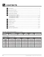
Skyblade SHOP PROP 0618-5 Installation Manual Download Page 8

SKYBLADe FANS 

-  

Where Form Follows Function

MoUNTiNg CoNSiDeRATioNS

3.1 General Mounting

Each type of mounting system requires a specific mounting bracket. Most are available from Skyblade 

Fans. Check with the contractor, building owner, or architect to ensure the structure is sound and 

will support the weight of the fan before beginning installation. Skyblade Fans provides guidelines for 

mounting fans; however, it is the sole responsibility of the building owner and installer to ensure the 

safety of the mounting system, that the building structure is sound, and the installation complies with 

all federal, state, and local codes.

3.2 Weight

A Standard 1.35-horsepower, Shop Prop Series 12 foot 5-blade fan and mounting assembly weighs 

about 114 pounds. In inverted-blade applications designed to blow air upward, there is an additional 

downward force of about 80 pounds due to fan thrust. We recommend applying a safety factor of 2 

times the stated hanging weight of the fan when determining the capabilities of the building structure.

3.3 Torque

The maximum torque that must be handed by the mounting system and the building structure will 

occur at the fans startup. For a 12 foot fan, maximum potential startup torque is 300 ft-lbs. Skyblade 

Fans use a soft-start technology which allows the rpm to ramp up as desired over 60 seconds. The 

event of this max torque being applied is unlikely and will only apply due to a failure of the variable 

frequency drive and its soft start technology.

3.4 Safety Cable

A Skyblade fan should never be run without proper installation of Safety Cables. These are supplied 

with every fan. You must install safety cable for warranty to be in effect.

3.5 Guy Wires

While in operation a fan can sway due to minor imbalance or because of wind. Since the mounting 

system is capable of swiveling, it will not stop fan movement, so it is important that the guy wires be 

installed properly. Proper installation includes the angle and tension of the guy wires. See page 22-23 

for more information.

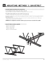
3.6 Universal Mounting Hardware

We recommend mounting the fan to a unistrut or angle iron spanning between trusts, however, this is 

not always possible in buildings with pitched roof construction. For this reason, our universal mounting 

system is designed to allow the fan to hang in a level position perpendicular to the ground by rotating 

the upper yoke 90 degrees. 

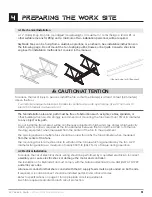
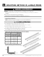
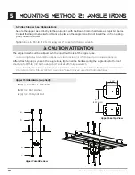
When cutting or drilling into a wall or ceiling, take care not to damage electrical wiring or other utilities.

Lorsque vous coupez ou percez un mur ou un plafond, prenez garde à ne pas endommager les fils 

électriques ou d’autres services publics.

Select a location that is free from obstructions that may interfere with the fan’s operation. 

Choisissez un emplacement qui est libre de tout obstacle pouvant interférer avec le fonctionnement 

du ventilateur.

CAUTION/ATTENTION

!

Summary of Contents for SHOP PROP 0618-5

Page 1: ...ws Function Where Function Where Form F Where Form Follows Fu Form Follows Function W Follows Function Where Function Where Form F Where Form Follows Fu Form Follows Function W Follows Function Where Function Where Form F Where Form Follows Fu Form Follows Function W Follows Function Where Function Where Form F Shop PROP Series 6 16 INSTALLATION MANUAL Custom Designed Reduced Maintenance STOL Tech...

Page 2: ...n accordance with all applicable codes and standards including fire rated construction Failure to comply could result in personal injury electric shock death fire and or property damage Before attempting installation servicing or cleaning unit switch power off at the service panel and lock the service disconnecting means to prevent power from being switched on accidentally Pour réduire le risque d...

Page 3: ...es outils et ne pas les utiliser à des fins autres que celles prévues par le fabricant This unit has an unguarded impeller Do not use in locations readily accessible to people or animals Cet appareil possède une roue sans surveillance Ne pas utiliser dans des endroits facilement accessibles pour les personnes ou les animaux Use this unit only in the manner intended by the manufacturer If you have ...

Page 4: ...17 lbs 8 kg 1030 5 10 3 0M Fan 8 203 mm 60 1524 mm 9 229 mm 21 lbs 10 kg 1236 5 12 3 6M Fan 8 203 mm 60 1524 mm 9 229 mm 24 lbs 11 kg 1443 5 14 4 3M Fan 8 203 mm 60 1524 mm 9 229 mm 27 lbs 12 kg 1649 5 16 4 9M Fan 8 203 mm 60 1524 mm 9 229 mm 30 lbs 14 kg 1 Fan Diagram 6 2 Important Information 7 3 Mounting Considerations 8 4 Preparing the Work Site 9 5 Mounting Method 1 Unistrut 10 Mounting Metho...

Page 5: ... C D D TBP Upper Yoke DRAWN DATE 19 04 10 DRAWN BY TH PART NUMBER 6001 S REV _001 THIS DRAWING IS THE EXCLUSIVE PROPERTY OF SKYBLADE FAN COMPANY AND CANNOT BE REPRODUCED OR DISCLOSED TO ANY THIRD PARTY WITHOUT THE AUTHORIZATION OF SKYBLADE FAN COMPANY MATERIAL 1 5 Steel RAL 9006 ALL DIMENSION ARE IN INCHES UNLESS OTHERWISE STATED 5 Gripple Fasteners 4 15 Guy Wires 1 5 Safety Cable Gripple Packet R...

Page 6: ...ousing for the motor and gear reducer E Airfoil Provides air movement F Wingtip Fence Improves air movement efficiency by reducing drag SERIES SP SP SP SP SP SP DIAMETER 6 1 8M 8 2 4M 10 3 0M 12 3 6M 14 4 3M 16 4 9M BLADES 5 5 5 5 5 5 VOLTAGE INPUT 120 1 230 1 230 3 460 3 120 1 230 1 230 3 460 3 120 1 230 1 230 3 460 3 120 1 230 1 230 3 460 3 120 1 230 1 230 3 460 3 120 1 230 1 230 3 460 3 Model N...

Page 7: ... the fan closer than 15 of its diameter to any object or its path If this is an issue mounting extension bars and smaller fans are available from Skyblade Fans 2 3 Fire Suppression Systems and Fan Placement If installing Fans in a location where fire sprinklers are in place do not interfere with their correct operation Fans should be located in the center of each sprinkler quadrant and no less tha...

Page 8: ...0 seconds The event of this max torque being applied is unlikely and will only apply due to a failure of the variable frequency drive and its soft start technology 3 4 Safety Cable A Skyblade fan should never be run without proper installation of Safety Cables These are supplied with every fan You must install safety cable for warranty to be in effect 3 5 Guy Wires While in operation a fan can swa...

Page 9: ...ent The spacing between multiple fans should be no less than 2 5x the fans diameter when measured from the center of the fans The mounting structure must be able to withstand the torque which is generated by the fan A 20 diameter fan generates a maximum of nearly 300 ft lb 406 7 N m of torque during operation 4 2 Electrical Installation To reduce the risk of electrical shock wiring should be perfo...

Page 10: ...n mounting point Minimum Unistrut Size W x H x T Qty of Unistrut Needed 8 2 4m 1 5 8 2 Support Directly From Building Structure All mounting instructions assume that the building structure from which the fan will be hung is of sound construction undamaged and capable of supporting loads of up to 650 lbs 295 kg It is the sole responsibility of the customer to verify that the building s structure is...

Page 11: ...a structure du toit à chaque extrémité Fasten the unistrut to the roof structure mounting points at each end with customer supplied Grade 5 hardware as shown Fixez l unistrut aux points de fixation de la structure du toit à chaque extrémité avec le matériel de qualité 5 fourni par le client comme illustré ATTENTION Do not tighten the hardware until the upper yoke has been mounted to the unistrut G...

Page 12: ...an from a single purlin truss or bar joist Ne pas installer le ventilateur à partir d une seule panne botte ou solives Unsupported angle iron spans should not exceed 12 3 7m Non pris en charge travées de fer d angle ne doit pas dépasser 12 pi 3 7 m Do not install motor and hub assembly directly on angle iron Ne pas installer moteur et moyeu directement sur cornière CAUTION ATTENTION 6 1 8m or less...

Page 13: ...Together if span is longer than 8 If the angle iron span is 8 2 4m or less proceed to step 5 6a on the following page If the angle iron span is longer than 8 2 4m it is necessary to use double angle irons Locate the center of the angle iron length Drill 9 16 1 4cm diameter hole through the center of the vertical wall of the angle iron Drilling through a total of four angle irons Place two drilled ...

Page 14: ...c 4 2 1 2 Square Washer see diagram d 4 1 2 Nylock Nut Do not install the fan from a single purlin truss or bar joist Ne pas installer le ventilateur à partir d une même purlin botte ou solives The angle irons must be fastened to the roof structure at each end Les cornières doivent être attachés à la structure de toit à chaque extrémité Fasten the angle irons to the roof structure mounting points ...

Page 15: ...iagram d 4 1 2 Nylock Nut Do not install the fan from a single purlin truss or bar joist Ne pas installer le ventilateur à partir d une même purlin botte ou solives The angle irons must be fastened to the roof structure at each end Les cornières doivent être attachés à la structure de toit à chaque extrémité Fasten the angle irons to the roof structure mounting points at each end with customer sup...

Page 16: ...érieur de la culasse supérieure After attaching upper yoke to the angle irons tighten all the bolts securing the angle irons to the roof structure to 90 ft lb 122 N m using a 3 4 socket with torque wrench Après l avoir fixée culasse supérieure aux cornières serrer tous les boulons de fixation des cornières à la structure du toit à 90 lb pi 122 Nm avec une prise 3 4 avec une clé dynamométrique CAUT...

Page 17: ...e upper yoke to the I beam with the Clamping Plate hardware shown below Tighten the bolts to 90 ft lb 122 N m using a 3 4 socket and torque wrench Proceed to Hanging the Fan on pg 21 Clamping Plate Hardware supplied a 4 1 2 13x2 1 2 GR 5 Bolt b 8 1 2 Flat Washer c 4 1 2 13 Nylock Nut d 2 Clamping Plate a b c b d Install the Clamping Shims only if the thickness of the I beam flange exceeds 3 8 1cm ...

Page 18: ... should be placed on both sides of the plate for each bolt 5 12 Pre Drill Angle Iron Brackets Holes Your angle iron should be cut to allow 1 2 1 27 cm clearance between the end of the angle iron and the purlin you are mounting to Drill one 9 16 1 4 cm diameter hole centered vertically exactly 1 2 54 cm from the edge on both ends of the vertical wall of the angle iron Drill a second hole exactly 3 ...

Page 19: ...faces of the purlin brackets 5 15 Attach Upper Yoke to Angle Iron Attach the upper yolk to the angle irons using the provided 1 2 grade 5 bolts washers and nylock nuts See section 5 7 Attach Upper Yoke to Angle Iron to continue installation Purlin Bracket Hardware per set supplied a 2 1 4 Formed Steel Purlin Bracket b 2 1 4 Steel Purlin Backplate c 16 1 2 13 1 3 4 GR 5 Bolt d 16 1 2 Nylock Nut e 3...

Page 20: ...GR 5 Bolt b 4 1 2 Flat Washer c 2 1 2 13 Nylock Nut 6 2 Secure Upper Safety Cable Secure the safety cable to the I beam or angle iron by wrapping the safety cable around it threading the cable through the 17 32 open hole on the top of the extension tube and securing the ends with the gripple fastener as shown The cable must have as little slack as possible Securely tighten the gripple Cable End De...

Page 21: ...oîte de vitesses ce qui peut entraîner des dommages ou une durée de vie raccourcie Ne pas installer le niveau annulera la garantie du fabricant WARNING AVERTISSEMENT 6 3 Attach the Motor to extension tube Attach the lower yoke on the chassis to the bottom of the extension tube with the Lower Yoke Hardware as shown Tighten bolts to 90 ft lbs 122 N m using a 3 4 socket with torque wrench Lower Yoke ...

Page 22: ...m reference Eye Hook illustration on page 23 1 Slide the unlooped end of the guy wire through the eye hook 2 Feed the wire through the loop on the other end of the wire 3 Pull tight so the wire tightens on the eye hook Attach each guy wire to the loop on the mid section of the motor 1 Slide the gripple fastener as supplied over the opposite end of the wire 2 Feed the end of the guy wire through th...

Page 23: ...ok Ceiling a Beam Clamp b Eye Hook c Gripple Wire Loop Gripple Maximum Angle Gripple Hook Tab Motor Make certain all electrical cords are not obstructed by guy wires Assurez vous que tous les câbles électriques ne soient pas obstruées par des haubans WARNING AVERTISSEMENT a Gripple Hook Tab b Guy Wire c Gripple Fastener a b c a c b Ceiling Beam 45 Maximum Guy Wire 1 2 3 4 5 6 B C D ...

Page 24: ...5 Soc Cap 5 16 18 x 3 4 c 10 Zinc Split Lock Washer 5 16 c b a To reduce the risk of personal injury do not bend the blade brackets when installing the brackets balancing the blades or cleaning the fan Do not insert foreign objects in between rotating fan blades Pour réduire le risque de blessure ne pas plier les crochets lame lors de l installation les crochets l équilibre entre les lames ou de n...

Page 25: ...SKYBLADE FANS Where Form Follows Function 25 8 installing Blades 8 1 Attach Blades to Hub Slide blade onto struts until blade holes and strut holes are aligned ...

Page 26: ...Cap 5 16 18 x 3 4 c 12 Zinc Split Lock Washer 5 16 ATTENTION Upon completion of the mechanical installation of the fan and before powering on spin the fan around multiple times by hand to ensure all brackets are clear from contact with other parts on the fan Thoroughly inspect the hub the bolts and brackets within the hub to guarantee clear and proper rotation If you find that the fan has a bracke...

Page 27: ...ps on end of blade after blade has been securely attached to the strut Fasten wingtip to blade using a 10 32 X 5 8 Button Cap 8 installing Blades 8 3 Wingtip Assembly Wingtip Hardware Kit supplied a 5 10 32x3 8 BTN Cap Screw Wingtip Wingtip Blade BTN Cap Screw ...

Page 28: ...oltage unbalance voltage swells rapid voltage change flicker superimposed signals harmonic voltages supply voltage variations voltage dips and frequency time deviation SkyBlade Fan Company n est pas responsable des perturbations de tension en référence explicite aux interférences magnétiques électroniques EMI Les perturbations de tension se réfèrent aux surtensions transitoires aux déséquilibres d...

Page 29: ...ins supply from line inputs at the fan controllers disconnect L1 L2 L3 Wait three 3 minutes for capacitors to discharge to safe voltage levels Darkened display LEDs are NOT an indication of safe voltage levels Failure to do so many result in personal injury or death DO NOT DISASSEMBLE THE MOTOR OR ITS ONBOARD DRIVE Doing so greatly increases the risk of shock Les contrôleurs de ventilateur contien...

Page 30: ...se installation CAUTION ATTENTION IMPORTANT Check that the correct input voltage is being sent to the fan See rating labels on the motor for acceptable voltage A blown fan due to incorrect input voltage is NOT covered under SkyBlade warranty WARNING AVERTISSEMENT Exercise caution and common sense when powering the fan Do not connect the fan to a damaged or hazardous power source Do not attempt to ...

Page 31: ...elow 9 3 Input Power Cable Wiring Schematics IMPORTANT Grounding of the incoming power on the motor is required NOTE Skyblade Suggests using a field supplied fused disconnect switch 1 Phase Voltage 120V 1Ph 230V 1Ph 3 Phase Voltage 230V 3Ph 460 3Ph Motor wire can be ran through the wire hole on the chassis then alongside or within the extension tube See Controller Data Sheet 6 Core Shielded Conduc...

Page 32: ...iring to a Fire Alarm Panel If the installation of the fan is required to be wired to a fire alarm emergency shut off an external relay will have to be placed by a fire suppression specialist between the voltage line feed and the fan s FIRE SUPPRESSION SYSTEM MOTOR Power Supply ...

Page 33: ...ng at the motor controller and from the controller to the supply b Do not run your controller and sensitive equipment on the same power line c Install properly sized EM RFI filter d Contact Customer Service at 1 586 806 5107 5 LED indicator is not blinking in normal fashion Please contact Skyblade Fans customer service to resolve issue WARNING AVERTISSEMENT Electrical Shock Hazard RISQUE D ÉLECTRO...

Page 34: ...e fan making any noise End of troubleshooting Yes Yes No No No Check splices and wiring at the controller Is the wiring correct No Fix incorrect wiring No Yes Yes No Check controller wiring sheet Is the wiring correct Fix incorrect wiring No Yes Check all brackets and bolts Ensure bolts are torqued to the proper rating and brackets are free to spin without collisions KEY Start Question Process Que...

Page 35: ...is low at splice of the fan motor Under volt may be occurring a line reactor may need to be placed to reach correct voltage Vibration 8 Blinks Second Check all brackets and bolts Ensure bolts are torqued to the proper rating Overtemp 7 Blinks Second If multiple fan diameters are being used make sure the correct blades are on the motor Verify that no external disturbances are occurring with the bla...

Page 36: ... Risk of fire electric shock or injury to persons during cleaning and user maintenance Risque d incendie de choc électrique ou de blessures lors du nettoyage et de l entretien par l utilisateur Disconnect the appliance from the power supply and allow sufficient time for electrical discharge before servicing Débranchez l appareil de l alimentation électrique et laisser suffisamment de temps pour la...

Page 37: ...SKYBLADE FANS Where Form Follows Function 37 11 User Servicing Instructions Maintenance Log Replacement Part List DATE MAINTENANCE PERFORMED REPLACEMENT PARTS REQUIRED PART NO DESCRIPTION ...

Page 38: ...38 SKYBLADE FANS Where Form Follows Function Notes ...

Page 39: ...SKYBLADE FANS Where Form Follows Function 39 Notes ...

Page 40: ... SkyBlade and SkyBlade Fans are the trademarks of SkyBlade Fans SkyBlade Fan Company Where Form Follows Function 24501 Hoover Road Warren Michigan 48089 USA 1 586 806 5107 sales skybladefans com www SkyBladeFans com ...

Reviews: