background image

12

Flying 

Craft/Remote Link

Before flying, the craft and the remote must be linked together and the gyroscopes on 

the craft must be allowed to calibrate.

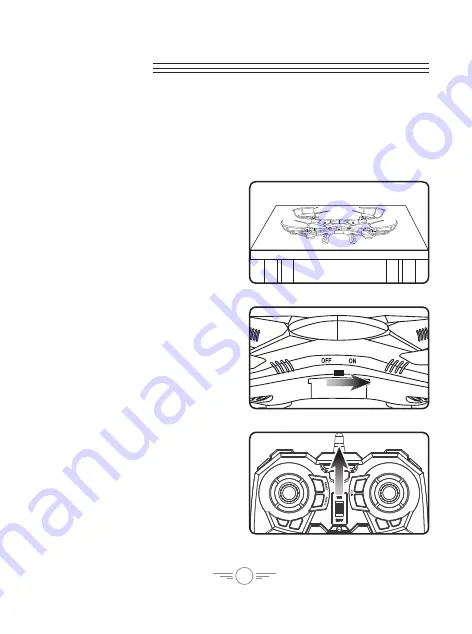
Begin with the craft and remote powered OFF.

Step 2

Power the craft ON.

 The LED formation 

lights will blink in unison as the craft 
searches for a signal from the remote. 

Step 1

Place the craft on a flat, level surface. 

This is necessary for the craft’s 
gyroscopes to properly align.

Step 3

Power the remote control ON.

 The light 

on the remote will blink as it searches 
for the signal from the craft. 

An audible chime will sound when the 
remote and the craft have linked with 
each other.

Summary of Contents for FALCON 2 PRO

Page 1: ...User s Guide for Model DRC377 v1742 01 ...

Page 2: ...uipment does cause harmful interference to radio or television reception which can be determined by turning the equipment off and on the user is encouraged to try to correct the interference by one or more of the following measures Reorient or relocate the receiving antenna Increase the separation between the equipment and receiver Connect the equipment into an outlet on a circuit different from t...

Page 3: ...raft Remote Link Trim Adjustment 14 Setting Trim Countering Drift Flying Tips Features 16 Tips for Safe Operation Speed Setting Flips Tricks Headless Mode Camera Memory Card 18 Video Photos SD Card Install Removal View Photos Video on a Computer Camera Angle Adjustment Troubleshooting 20 Gyroscope Recalibration Remote Reset Repair 22 Parts Replacement Rotor Replacement Customer Support 23 Contact ...

Page 4: ...stance up to 150 feet Headless Mode LED navigation lights Operating time 6 8 minutes Charge time 40 50 minutes Includes 2 4 GHz remote control requires 6 AA batteries not included Built in rechargeable lithium polymer battery USB cable for battery recharge 4GB SD card Screwdriver 4 replacement rotors User s guide warranty Falcon 2 Pro ...

Page 5: ...erview Craft Layout Features FRONT FRONT Battery Compartment Camera Rotors White rotors indicate front of craft Power Switch LED Lights White LEDs indicate the front of the craft Rotor Guards Landing Skids ...

Page 6: ...own using the included screwdriver and wide head screws 1 2 Insert pegs into the holes on the underside of the body as shown Landing Skids Small Phillips head Screwdriver x4 Wide head Screws Assembly Instructions ...

Page 7: ...ards Tighten down using the included screwdriver and the standard screws Small Phillips head Screwdriver x4 Standard Screws 2 Insert the two pegs on the underside of the rotor guard into the upper body as shown 1 ...

Page 8: ... right Headless Mode press down Reset Speed Press to change craft speed setting Press and hold to reset craft to factory settings Photo Press to take a photo Video Press to take video Flip Press and move the Right Thumbstick to perform a flip Roll Trim Correct left right drift Yaw Trim Correct left right rotational drift Pitch Trim Correct forward backward drift Power Switch Indicator Remote Contr...

Page 9: ...9 Insert 6 x AA Batteries not included Use screwdriver included and remove battery cover Remote Battery Installation ...

Page 10: ...ft is powered OFF then remove the battery cover Step 3 Attach the plug on the battery to the plug on the charging cable Be sure to match the plugs correctly or damage may occur Step 2 Disconnect the power plug connecting the battery to the craft It is strongly recommended to remove the battery when charging This will reduce the chance of damage or injury ...

Page 11: ... battery in its bay reconnect the power plug from the battery to the craft and close the battery cover Be sure to match the plugs correctly and securely close the battery cover or damage may occur Step 4 Plug the charging cable into the USB port of a powered ON computer or USB power adapter not included The battery will now charge ...

Page 12: ...raft ON The LED formation lights will blink in unison as the craft searches for a signal from the remote Step 1 Place the craft on a flat level surface This is necessary for the craft s gyroscopes to properly align Step 3 Power the remote control ON The light on the remote will blink as it searches for the signal from the craft An audible chime will sound when the remote and the craft have linked ...

Page 13: ... the craft If you notice a tendency to drift you may need to adjust the trim controls to fine tune the handling see next section When You re Done Flying After safely landing keep the Left Control Stick throttle in the lowest position OFF and power OFF the remote first This will ensure that no signals are accidentally sent to the craft reducing the chance of injury After this is done it is safe to ...

Page 14: ...while attempting a stable hover Try to avoid making any exaggerated movements with the flight controls Adjust one trim setting at a time to avoid confusion Remember the white rotors and LED lights indicate the front of the craft Adjusting the trim will help with drift but it will not entirely eliminate it Turbulence and other environmental conditions may influence the craft s flight characteristic...

Page 15: ...15 Craft pitches angles forward or backward Adjust Pitch Trim Craft banks rolls left or right Adjust Roll Trim ...

Page 16: ...move the controls slowly and deliberately to get used to the craft s flying characteristics Try using one control at a time Practice basic flight operations like take off hovering and landing If you crash throttle down the engines IMMEDIATELY to reduce the chance of damage or injury If anything obstructs the propellers for any reason throttle down IMMEDIATELY and safely clear the obstruction Check...

Page 17: ...ny direction Headless Mode Headless Mode changes the default orientation of the craft where the red LEDs red rotors indicate the front of the craft Instead the craft will reorient its front based on the first Right Control Stick input from the user This can be useful if you become disoriented while flying or cannot visually determine which direction is true front To activate Headless Mode press th...

Page 18: ... the remote The indicator light will turn green for as long as the camera is recording Press the video button again to stop recording video the light will turn back to red Photos To take a single image press the Photo button once The indicator light will turn from red to green then back to red Press and hold the Photo button to take a 3 photo burst The indicator light will flicker green 3 times th...

Page 19: ...y occur Gently push against the Micro SD card until it clicks into or out of the card slot Be sure to insert correctly or damage may occur Connect to a USB port of a computer Use the computer s file browser to access photos and videos SD Card Install Removal View Photos Video on a Computer Camera Angle Adjustment ...

Page 20: ...hen they have stopped blinking and turn solid again the recalibration is complete and the craft is ready to fly Remote Reset If you are still having difficulty flying it may help to reset the remote This will clear the trim settings and reset them to default Do not attempt to do this while flying Safely land the craft before attempting this procedure Press and hold the Reset button for 3 4 seconds...

Page 21: ...cted Be sure the remote has an unobstructed line of sight to the craft Remain within the remote s 150 ft range Craft drifts while in flight Trim not set or needs adjustment Adjust trim settings see pg 12 Craft is difficult to control or flies erratically Gyroscopes misaligned Trim settings too far out of adjustment Damage to body rotors or other major components Recalibrate gyroscopes see previous...

Page 22: ...lacement Use a small Phillips head screwdriver included to remove and replace the center screw connecting the rotor to the motor shaft It is extremely important to use the correct rotor A or B for replacement Using the incorrect rotor will make the craft impossible to control The marking can be seen on the underside of the rotor near the shaft REMINDER Pilots are responsible for any damage caused ...

Page 23: ... questions fréquemment posées consultez la rubrique d assistance sur www gpx com Contact Information Website www gpx com Email Support prodinfo dpiinc com Email Parts partsinfo dpiinc com Phone Support 1 888 999 4215 Warranty See included 30 Day Warranty for warranty information Warranty and the most up to date version of this User s Guide can also be found at http gpx com drc377 html Protect for ...

Reviews: