Skov DOL 31 Technical User Manual Download Page 6

DOL 31 Speed Controller

6

Technical User Guide

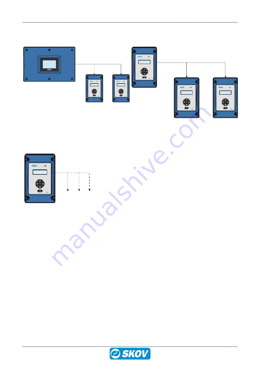
1.2 DOL 31 Automatic – Slave mode

Controlled by a 0-10 V input signal.

Controlled by a SKOV A/S controller

Controlled by DOL 31

1.3 DOL 31 manual control

Fan

Light

Fan

Controlled manually with setting via the keyboard. Output can be
set to 0 to 100 %.

Summary of Contents for DOL 31

Page 1: ...DOL 31 Speed Controller Technical User Guide 612061 2022 10 17...

Page 2: ...manual may be reproduced in any manner whatsoever without the expressed written permission of SKOV A S in each case All reasonable efforts have been made to ensure the accuracy of the information con...

Page 3: ...1 13 4 4 6 Circuit diagram controller to DOL 31 13 4 4 7 Cable plan DOL 31 Master and Slave 14 4 4 8 Circuit diagram DOL 31 Master and Slave 14 5 User guide 15 5 1 Operation 15 5 2 Alarm lamp 15 5 3 D...

Page 4: ...ght 24 7 12 Language 24 7 13 Version Information 24 8 Settings 25 8 1 Factory settings 25 8 2 Functions in menu mode 25 8 3 Table relating to DOL 12 temperature sensor control 26 9 Replacing Triac 27...

Page 5: ...Slave mode in which the DOL 31 output is controlled by a 0 10 V input signal Manual control in which the DOL 31 output is set manually by means of the keyboard on the front In addition DOL 31 has an...

Page 6: ...1 2 DOL 31 Automatic Slave mode Controlled by a 0 10 V input signal Controlled by a SKOV A S controller Controlled by DOL 31 1 3 DOL 31 manual control Fan Light Fan Controlled manually with setting v...

Page 7: ...put 1 24 V alarm relay 1 230 V control relay 1 Supplied with 1 DOL 12 temperature sensor 3 plastic glands M25 and 3 plastic nuts M25 130172 DOL 31 speed controller 16 A 0 10 V input or DOL 12 input 1...

Page 8: ...Guide 3 Mounting guide 3 1 Recommended tools Below follows a list of tools recommended for installation of the DOL 31 Item Description Cordless drill Drill kit Hammer Marker pen Multimeter Tape measu...

Page 9: ...ree space around the cabinet 10 cm D on the right side for operation of the AUT 0 MAN Auto Manual change over switches 27 cm E above the cabinet so that the front panel can be placed here during servi...

Page 10: ...r is not included 4 1 Cabling Cables are led through plastic glands in the bottom section It is recommended to use armored cable in loca tions where there is a risk of rodent attacks 4 2 Dismantling t...

Page 11: ...L 31 X2 0 V X3 0 10 V or 10 0 V output signal X4 0 V X5 24 V DC output X6 0 V X7 Alarm relay NO X8 Alarm relay COMMON X9 Alarm relay NC X10 Control relay NO X11 Control relay COMMON X12 Control relay...

Page 12: ...Code Color Standard BK Black Color coding on wires are in accor dance with standard IEC 60757 Letter codes to identify colors used on drawings diagrams labelling etc BN Brown RD Red OG Orange YE Yell...

Page 13: ...DOL 31 Speed Controller Technical User Guide 13 4 4 5 Cable plan controller DOL 31 4 4 6 Circuit diagram controller to DOL 31 31 6 8 A 10 A fuse 31 16 A 16 A fuse DOL DOL DOL31...

Page 14: ...chnical User Guide 4 4 7 Cable plan DOL 31 Master and Slave 4 4 8 Circuit diagram DOL 31 Master and Slave 31 DOL 31 16 A 16 A fuse DOL DOL31 6 8 A 10 A fuse DOL31 From X3 on Master From X4 on Master T...

Page 15: ...is on when DOL 12 temperature sensor is dis connected Low temperature alarm Low supply frequency DOL 12 temperature sensor is dis connected High temperature alarm High supply frequency 5 3 Display Aut...

Page 16: ...turn key Return is used for Returning to previous level or function Data remains unchanged OK key OK is used for Selecting function Confirming and saving data 5 6 Menu Survey Set temperature output Se...

Page 17: ...from the temperature sensor DOL 31 automatically adjusts according to the set tem perature Set mode Automatic Master 6 1 1 Set temperature Set required temperature DOL 31 automatically adjusts accordi...

Page 18: ...quire a minimum voltage Set output 26 6 4 Minimum regulation of AC output Setting minimum power on output The setting is made as a percentage of the supply voltage Control of the output by pressing th...

Page 19: ...maximum power on output The setting is made as a percentage of the supply voltage Control of the output by pressing the up or down key Min setting 50 100 cannot be set higher than 50 Set maximum outp...

Page 20: ...o activate alarm relay and alarm lamp Alarm is released in case of high and low tem perature The function is only active in Automatic master mode Set temperature alarm 4 C 16 20 24 Temp C Required tem...

Page 21: ...s that the control relay in the below example is deactivated again when the temperature increase to 12 5 C Set control temperature 8 C 1 Active control relay 0 Not active control relay Example Control...

Page 22: ...aximum analog output 10 V The analog output follows the calculated ventilation percentage Example DC MIN 10 V DC MAX 0 V DC MIN 0 V DC MAX 10 V 7 7 Selecting temperature scale Select whether the tempe...

Page 23: ...DOL 31 output will be switched off if the analogue input signal is lower than this turn off limit See section Set turn off limit 24 This means that it is not possible to have both turn off mode and t...

Page 24: ...nd the DOL 31 output will remain at minimum not in verted or maximum inverted Turn off No 0 5 V Turn off limit Not inverted Relative voltage between 0 2 V Inverted Relative voltage between 8 10 V 7 10...

Page 25: ...trol temperature offset 10 C 10 C 10 C P band 2 C 4 C 10 C Minimum DC output 0 V 0 V 10 V Maximum DC output 0 V 10 V 10 V Input 0 10 V Temperature scale Celsius Safety mode Yes Invert No Language Engl...

Page 26: ...5 9 03 3 34 0 32 91 6 37 23 16 27 4 71 46 8 82 3 29 1 31 92 6 30 24 15 79 4 64 47 8 62 3 24 2 30 96 6 23 25 15 34 4 57 48 8 43 3 19 3 30 02 6 16 26 14 90 4 50 49 8 24 3 14 4 29 11 6 09 27 14 48 4 43 5...

Page 27: ...sing the triac to break 1 Order 130828 DOL 31 5 pcs all purpose triac consisting of 5 individual triacs in a bag 2 Disconnect the supply voltage to DOL 31 3 Remove the defective triac 4 Mount the new...

Page 28: ...cleaner solvents corrosive caustic agents 10 2 Recycling Disposal Products suitable for recycling are marked with a pictogram It must be possible for customers to deliver the products to local collect...

Page 29: ...t the AUT 0 MAN switch is set on the re quired function Fans run 100 Light cannot be adjusted up down Check that the switch is set on the required function or see section Replacing Triac 27 The temper...

Page 30: ...60 230 V triac output Mechanical Cable knock out punches 7 pcs 25 5 mm for M25 cable glands Environment Operating temperature C F 0 to 40 14 to 113 Storage temperature C F 25 to 60 13 to 140 Ambient h...

Page 31: ......

Page 32: ...612061 2022 10 17 en US Made in Denmark SKOV A S Hedelund 4 Glyng re DK 7870 Roslev Tel 45 72 17 55 55 www skov com E mail skov skov dk...

Reviews: