


INSTALLATION INSTRUCTIONS TO THE INSTALLER
A.) Hanging the unit.
B.)
1) Remove ceiling tile where unit is to be located and remove any adjacent tiles that
would be helpful in handling the unit while positioning it in the ceiling.
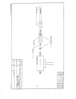
2) Secure suitable type material (such as slotted angle) in place. The material should
be capable of supporting the weight of the unit. Now attach all thread rods (3/8”
field supplied) to angle. The rods should have double nuts. See diagram #1 for
spacing of rods to ensure they will line up with hanger when unit is raised into the
ceiling.
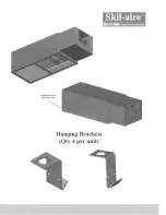
3) Next drill holes for hanger positioning screws. Hangers’ positions are marked on
the sides of the units. Do not mount hangers to the unit at this time. Note: if it is
possible to remover one of the 4’ T bar section from the ceiling, then the hangers
can be mounted prior to lifting unit into ceiling.
4) Now raise unit into the ceiling. The use of a high jack is recommended, once unit
is above the ceiling attach mounting brackets to unit and then attach all thread rods
to hangers. Once all thread rods are attached to hangers raise unit several inches
above the ceiling to allow placement of the grille into the ceiling grid. After grille is
in place lower unit just far enough for the frame to form an airtight seal with the
foam backing on the grille. The unit is now ready for electrical wiring or water
piping.
B) Installing Remote Condenser Fan
1) The remote condenser fan can be mounted using a hanger strap or with hangers
provided with the fan and short pieces of angle(field supplied)
2) Prior to hanging the condenser fan section mount the 2x4 junction box to the top of
the unit. Attach wiring harness and connect fan motor wires to the wiring harness
supplied.
3) It is STRONGLY recommended that a field supplied flexible duct connector be
used when attaching condenser section to the evaporator sections.
C) Electrical
All field wiring should be done by a qualified electrician and should meet all local codes.
Knockouts for the unit power, control wiring, and condenser fan are located in the top of the
unit directly above the control section. A wiring harness for the remote condenser fan is
supplied with the unit. The end of the harness with the stacons is attached to the control
section of the unit. Connect the stacons to spade terminal on the main contact on the load
side.


