SKF 94904 User And Maintenance Instructions Download Page 9

Setting air brake trip 

speed

Selecting speed range letter other than 

bypass will activate air brake  Air brake will 

stop air motor from operating if threshold 

speed setting is exceeded  Air motor will not 

restart until intentionally reset  Cause of 

pump overrun may be anything that will 

allow pump to run faster than normal such 

as, but not limited to the following:

Cavitation

Low fluid levels will allow pump to cavitate  

Pump will try to pump air instead of fluid into 

fluid lines 

Broken hose or fitting

Broken hose or fitting will cause loss in fluid 

pressure allowing pump to run faster than 

normal 

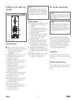
Setting speed

Remove selector cover (

87

) by removing 

screw (

88

) to gain access to selector 

knob (

84

Select bypass mode by positioning 

selector knob pointer (small round hole 

in face of selector knob) to face of 

labyrinth cover (

78

Determine speed of pump by counting 

number of strokes pump makes per 

minute with pump and air motor 

operating normally 

After determining normal operating 

speed of pump and air motor, consult 

setting legend on face of labyrinth  

cover (

78

), and find speed range closest 

to normal operating speed of air motor 

To allow for normal fluctuation in 

operating speed of air motor and pump, 

set selector knob to next highest speed 

setting 

Test pump in operation to make sure it is 

operating properly before leaving 

pumping system unattended 

Speed settings

       Bypass air brake  In bypass mode air 

brake does not provide any protection to 

pump or air motor  Air motor will 

continue to run at any speed   

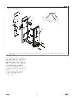
See 

Fig. 13


45 to 60 cycles/minute, air brake will trip 

turning off air motor when air motor 

speed reaches speed of  

45 to 60 cycles/minute 

30 to 45 cycles/minute, air brake will trip 

turning off air motor when air motor 

speed reaches speed of  

30 to 45 cycles/minute 

20 to 30 cycles/minute, air brake will trip 

turning off air motor when air motor 

speed reaches speed of  

20 to 30 cycles/minute 

15 to 25 cycles/minute, air brake will trip 

turning off air motor when air motor 

speed reaches speed of  

15 to 25 cycles/minute 

10 to 20 cycles/minute, air brake will trip 

turning off air motor when air motor 

speed reaches speed of  

10 to 20 cycles/minute 

5 to 15 cycles/minute, air brake will trip 

turning off air motor when air motor 

speed reaches speed of  

5 to 15 cycles/minute 

1)

2)

Air brake operation 

NOTE

Speed settings are not precision speed con-

trol settings for air motor  All speed settings 

are approximate and are not intended for use 

in precisely controlling speed of pump/pump 

tube combination  Precision control of pump 

operating speed is beyond scope of device 

NOTE

Operating air motor at speeds greater than 

45 cycles/minute is not recommended with 

air brake engaged  Operation at speeds 

greater than 45 cycles/minute will cause no 

harm to air brake, but may exceed limitations 

of timing circuit in air brake causing air brake 

to trip without apparent cause 

Fig. 13

1)

  Speed setting legend 

2)

  Speed setting dial 

NOTE

 Always shut off air supply before servicing air 

motor  Air motor in tripped condition is under 

pressure and may restart unexpectedly for 

one or two cycles 

9

Summary of Contents for 94904

Page 1: ...User and maintenance instructions Models 94904 94906 94908 94910 series B 4 1 4 6 8 and 10 in Air motors with air brake Date of issue January 2018 Form number 404239 Version 2...

Page 2: ...ng and operating air motor Air motor must be operated maintained and repaired exclusively by persons familiar with operating instructions Local safety regulations regarding installation operation and...

Page 3: ...n 2 9 1 4 in 235 mm 10 11 16 in 271 mm 22 3 4 in 577 mm 94904 75 cpm 1 6 in 152 mm 25 lbs 11 7 kg Buna N and Teflon 2 7 1 2 in 191 mm 8 11 16 in 221 mm 23 5 8 in 599 mm C 1 20 1 2 4 in 101 mm 4 in 101...

Page 4: ...4 Signal valve cap kit 31 Fig 5 Air signal valve 20 Fig 6 Trip indicator 48 Fig 7 Stop valve repait kit 91 Fig 9 Bleed assembly 67 Fig IPB1 Gasket and air filter 89 and gasket plate and check valves...

Page 5: ...244806 and 244808 Fig 12 Power valve spool and body 244802 NOTE Muffler element kit 84939 available for repair of muffler includes element felts and gasket NOTE Cylinder tube soft parts kit 84789 10...

Page 6: ...to top of pump tube outlet and tightly connect coupling nut to air motor piston rod 5 36 and 72 3 Attach tie rods to pump tube with four nuts 42 Leave nuts loose 4 Connect air supply 5 Slowly cycle pu...

Page 7: ...is within circle and stub end protrudes through X 11 3 After installing umbrella valve 63 long rubber stem of valve is to be removed leaving rubber ball end intact to secure valve to plate 11 4 When...

Page 8: ...byrinth plate inside Inspect labyrinth plate for any signs of blockage including but not limited to dirt grease oil or water that should be visible through clear laminating material 2 Keep all labyrin...

Page 9: ...on to pump or air motor Air motor will continue to run at any speed See Fig 13 1 45 to 60 cycles minute air brake will trip turning off air motor when air motor speed reaches speed of 45 to 60 cycles...

Page 10: ...f problem before resuming normal operation Resetting air brake after tripping 1 Turn off air supply to air motor 2 Press flush reset button located on right side of relay valve 17 with screwdriver or...

Page 11: ...structions 3 Torque to 50 in lbf 5 7 Nm After 24 hours retorque to 50 in lbf 5 7 Nm 4 Model 94904 4 1 4 in 113 mm air motor only 5 Torque to 10 12 ft lbs 13 5 to 16 2 Nm 6 Refer to page 4 for service...

Page 12: ...81 2 1 Optional tamper resistant cover 2 Single hole on 76 should align with single hole on 75 17 19 20 23 24 31 32 35 35 39 40 48 49 50 51 52 53 54 57 58 59 60 61 62 63 64 65 66 67 91 55 92 56 49 Fig...

Page 13: ...1 2 40 40 54 56 1 Note holes at 9 and 6 o clock positions 2 Molded pin on pump sleeve Position to about 7 o clock position as shown Fig 17 13...

Page 14: ...le adapter to piston rod using Loctite 242 Blue on threads Torque to 60 65 ft lbf 81 88 Nm Model 94904 only 21 5 68 69 70 71 72 Fig IPB5 Piston assembly models 94906 and 94908 Fig IPB6 Piston assembly...

Page 15: ...ant selector knob cover kit 94 may be used to cover air brake selector knob to prevent un authorized adjustment of air brake settings Kit consists of cover special screw and special driver for screw a...

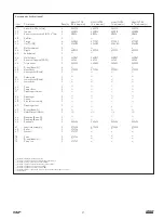
Page 16: ...051 50051 50051 50051 24 Screw 1 4 20 x 7 8 in 4 50850 50850 50850 50850 25 Tie rod 4 247295 12 12 12 26 Nut 4 247298 12 12 12 27 Screw 2 244995 244995 244995 244995 28 Gasket 1 6 6 6 6 29 Muffler bod...

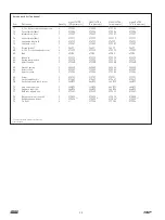
Page 17: ...1 4 4 4 4 53 Lower gasket Nitrile 1 3 3 3 3 54 Lower body 1 8 8 8 8 55 Piston 1 5 5 5 5 56 Pump sleeve 1 5 5 5 5 57 Diaphragm retainer 1 6 6 6 6 58 Diaphragm 1 6 6 6 6 59 Spring 1 6 6 6 6 60 Stop valv...

Page 18: ...102 82 Index pin 1 273391 273391 273391 273391 83 Spring compression 1 273392 273392 273392 273392 84 Selector knob 1 273380 273380 273380 273380 85 Washer spring 2 243845 243845 243845 243845 86 Sele...

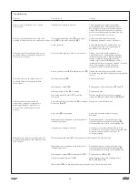
Page 19: ...t trip speed within three strokes Leaking diaphragm 58 Replace diaphragm Leaking upper gasket 51 Replace upper and lower gaskets 51 and 53 Upper piston quad ring 64 is leaking Replace quad ring Lamina...

Page 20: ...ery care has been taken to ensure the accuracy of the information contained in this publication but no liability can be accepted for any loss or damage whether direct indirect or consequential arising...

Reviews: