


VT-MODEM-2 Power, Phone Line, Self-Dial Connections:
DC Power Wiring
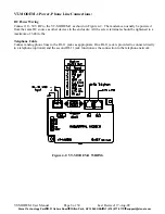
Connect 10 - 30 VDC to the VT-MODEM-2 as shown in Figure 4-3. The modem can usually be powered
from the same source as other devices in the enclosure. All the screw terminals should be tightened to a
maximum of 3.48 in-lbs.
Telephone Cable
Connect analog phone lines to the RJ11 jacks as appropriate. One RJ-11 jack is provided to connect directly
to a telephone (optional) and the second RJ-11 jack functions as the connection to the telephone network.
PLC Self-Dial I/O Connections
Connect a 10-30VDC signal to the ‘From PLC’ (trigger input) terminal. An OFF to ON transition of this
signal starts the auto-dialing sequence. The modem will call and remain connected while the signal is ON.
When the signal goes false, the modem will terminate the connection or the call in progress.
The ‘To PLC’ (on-line output) terminal will go ON (ON = user supplied VDC input) when a modem to
modem connection has been established and the proper ‘Acknowledge Message’ has been received.
Figure 4-3: VT-MODEM-2 WIRING
VT-MODEM User Manual
Page 9 of 30
Last Revised: 17-Aug-09
Sixnet Technology Park
331 Ushers Road
Clifton Park, NY 12065 USA
+1 (518) 877-5173