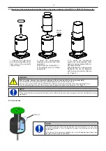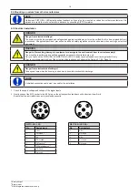
8.2 Mounting of the actual-position feedback unit on the valve actuators of the SISTO-C LAP.520/.530 type series:
8.3 Accessories
13
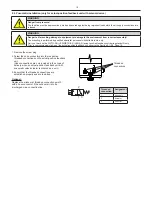
1. Remove the guide bush
and the actual-position feed-
back unit on the pneumatic
valve actuator.
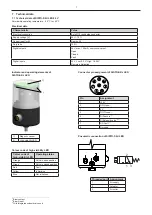
2. Screw the actual-position
feedback unit into the tread and
hand-tight.
With connection thread M18 x 1
in the actuator screw in thread
adapter first.
3. To adjust the connections
exactly, the actual-position feed-
back unit can be rotated further in
clockwise direction.
After adjusting the actual-position
feedback unit can be tightened
with the help of a wire pin (Section
8.3, Page 13).
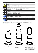
WARNING
Risk of injuries, damage to equipment or damage to the environment due to incorrect assembly!
The assembling must be performed by qualified specialist personnel with suitable tools.
Carry out work on the SISTO-SK-i LED/SISTO-SK-i LED AS-i actual-position feedback unit during standstill only.
Prior to commissioning/start-up of the actual-position feedback unit observe the Section 9.1-9.4, Page 16.
Adapter
M18 x 1
NOTE
When assembling the actual-position feedback unit, a sufficient distance to electromagnetic sources of interference must be
maintained.
Wire pin
NOTE
The bottom housing section and the adapter can be interlocked. To do this, insert
a wire pin (diameter ≈ 1 mm) through the opening in the housing into the hole in
the adapter.
This wire pin is an accessory available as a set with programming magnet and
lanyard with the article no. 42493506.


