MC1000e-R / T
www.siskiyou.com
siskiyou
1-877-313-6418
4
User’s Manual
3.0 Installation
CAUTION: MAKE SURE ALL CONNECTORS ARE SECURELY PLUGGED
IN BEFORE POWER IS TURNED ON. DO NOT REMOVE CONNECTORS
WHILE POWER IS ON. FAILURE TO DO SO CAN RESULT IN A SHORT
CIRCUIT AND PERMANENT DAMAGE TO THE SYSTEM.
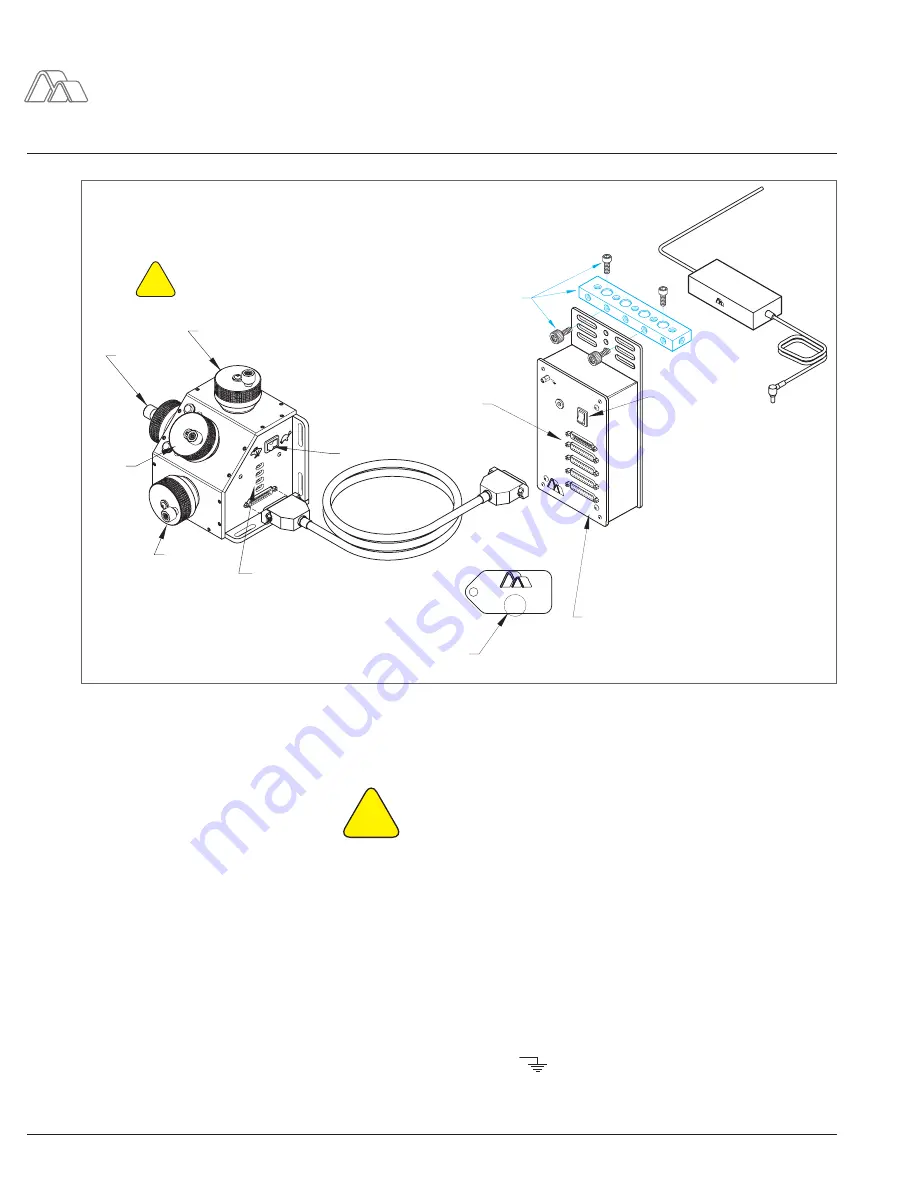
To install the MC1000e-R/T, please refer to Figure 1: Interface or the supplied
set up instructions. Supplied with the MC1000e-R/T are two ¼-20 screws that
can be used in securing both the controller and the junction box to the work
station.
It is advised to align Drive Axis No.3 of the controller towards the user. In doing
so, Drive Axis No. 1, 2, 3 and 4 are aligned respectively with the tilt, X, Y, and
Z axes. Each axis is label on the controller by a number. It is also advised to
add a ground wire onto the junction box and attach the free end of the wire to a
metal surface outside of the system. The lug to use is labeled by the electrical
symbol for “ground”:
!
*
1524-76:1-15/8
siskiyou
POWER ON
POWER IN
1
2
3
4
1
2
3
4
MC1000e-R/T CONTR
OLLER
(COMP
ATIBLE
WITH 76:1 GE
ARHEAD)
CONTR
OLLER
BB-5.0 construction
rail and hardware
used for mounting
control and junction
boxes, if needed.
4 screws provided,
BB-5.0 purchased
separately.
Low / High speed switch
Drive axis no.4
Drive axis no.2
Drive axis
no.1
Drive axis no.3
IMPORTANT: Make sure all
connectors are securely
plugged in before power
is turned on.
!
The motor/gearhead ID tag on
each motorized drive and
motorized stage shows the
gearhead ratio. See example:
Reverse polarity switches,
4 places
Power
switch
25 pin D connector
for motorized drive,
4 places
The junction box lid has been
marked to indicate the correct
motor/gearhead type to be
used with this controller.
MC1000e-R / T Setup Instructions
Figure 1: Interface
2
7021000s.eps
POWER AD
APTER


