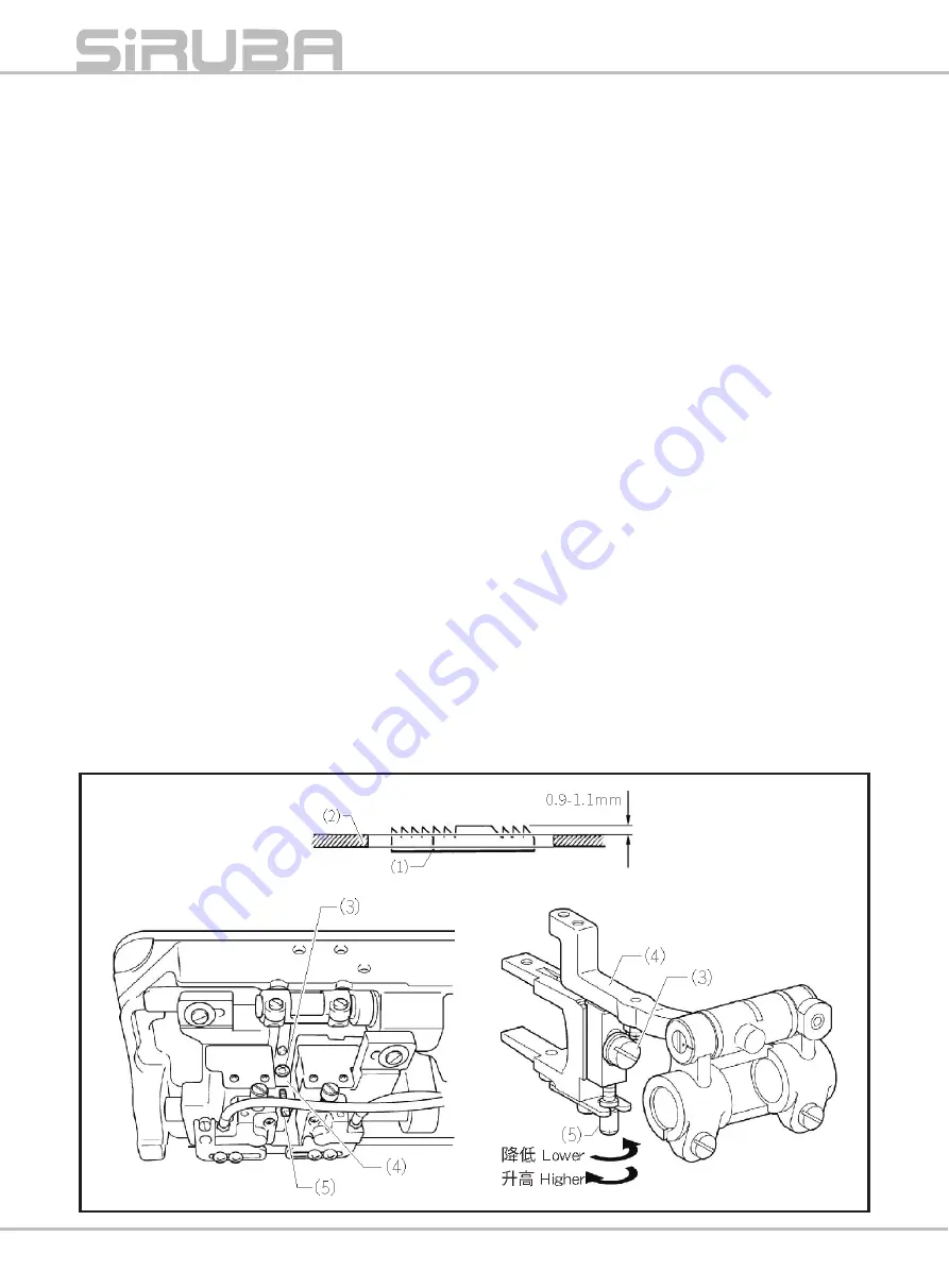
Siruba DT828L Manual Download Page 32

Feed dog height
Turn the machine pulley forward until the feed dog (1) is at 
its highest position, and then adjust so that the feed dog (1) 
protrudes 0.9-1.1 mm from the top of the needle plate (2)
1.Tilt back the nachine head
2.Loosen the screw (3) just enough so that the feed bar (4) can 

slide

3.Turn the height adjustment screw (5) as shown in the illustration 

to adjust the height of the feed dog (1)

4.Securely tighten the screw (3)
5.Recheck the height of the feed dog (1)

 If the feed is too high

The feed dog may touch the needle plate

The stitch length may become longer than the stitch length dial 

setting

Thread tightening may be poor when using thick threads

It may be difficult to obtain uniform stitch lengths for normal 

feed and reverse feed

Lower thread trimming errors may occur

 If the feed is too low

The stitch length may become shorter than the stitch length dial 

setting

It may be difficult to obtain uniform stitch lengths for normal 

feed and reverse feed

The feed dog may touch the movable knife

Large variations in stitch length may occur at slow and fast 

sewing speeds

送布⽛的高度


轉動手動輪,送布⽛(

1

)上升到最高位

置,此位置進行調整,使送布⽛(

1

)距

針板(

2

)上面

0.9-1.1mm

1.

放下縫紉機頭

2.

將螺釘(

3

)旋松一點,使送布台(

4

能滑動即可

3.

轉動高度調節螺釘(

5

),調節送布⽛

1

)的高度

4.

將螺釘(

3

)擰緊

5.

再次確認送布⽛(

1

)的高度

※ 送布⽛過高的情況
●送布⽛會碰到針板
●針跡長度會⽐實際針距大
●用粗線時,線鬆緊不良
●正送布與倒送布的線跡長度難能一致
●可能發生底線切線錯誤

※ 送布⽛過低的情況
●針跡長度會⽐實際針距小
●正送布與倒送布的線跡長度難能一致
●送布⽛碰動刀
●低速和高速縫紉的線跡長度差變大

P26

Summary of Contents for DT828L

Page 1: ...DT828L INSTRUCTIONS BOOK PARTS LIST...

Page 2: ...avoid injury High speed moving area Stay away and keep clear to avoid injury CAUTION Moving parts may cause in jury Operate with safety devices Turn off main switch before threading changing bobbin an...

Page 3: ...ention or in any manner other than that prescribed in the instruction manual 2 Never modify or alter the machine Any unauthorized change of the specification will not be covered by the warranty 3 Our...

Page 4: ...ing mechanism only and lock them well to secure the machine during the operation and service 3B Cable and Wire 1 The cables and wires must comply with the specification and requirement 2 The cables an...

Page 5: ...st disconnect the air supply and expel the air completely to avoid abrupt start 4 Check all screws and nut are fixed well after adjusting and replacement 5 A periodical cleaning is necessary Make sure...

Page 6: ...ON 1 NAMES OF MAJOR PARTS 2 INSTALLATION 3 PREPARATION BEFORE SEWING 6 SEWING 12 THREAD TENSION 13 CLEANING 17 ADJUSTING THE ROTARY HOOK LUBRICATION AMOUNT 18 STANDARD ADJUSTMENT 19 SERVICE PARTS POLI...

Page 7: ...M H M H H H Max sewing speed 3000 sti min 3000 sti min 3000 sti min 3000 sti min Max stitch length 4mm 5mm 4mm 5mm 7mm 7mm Presser foot height Lifting lever 7mm 7mm 7mm 7mm 7mm 7mm Automatic 8 12mm 8...

Page 8: ...cover 5 Bobbin winder 4 Cotton stand 3 Power switch 6 Operation panel 7 Machine pulley 8 Motor cover 9 Oil gage window 10 Reverse seam switch button Needle lever release button 245 275 11 Oil pan NAM...

Page 9: ...quipment such as televisions radios or cordless telephones otherwise such equipment may be affected by electronic interference from the sewing machine The sewing machine should be plugged directly int...

Page 10: ...hine head 2 Hinges 2pcs 3 Head rest NOTE Tap the head rest 3 securely into the table hole If the head rest 3 is not pushed in as far as it will go the machine head will not be suf ciently stable when...

Page 11: ...hold the base of the nozzle securely If your hold the end of the nozzle injury from the scissors may result The sewing machine should always be lubricated and the oil supply replenished before it is...

Page 12: ...g inward and then securely tighten the screws 1 Removing the bobbin Turn off the power switch before removing the bobbin The machine may operate if the treadle is depressed by mistake which could resu...

Page 13: ...hread path 4 Push the bobbin presser arm 3 toward the bobbin 1 5 Raise the presser foot with the lifting lever 6 Depress the treadle Lower thread winding will then start 7 Once winding of the lower th...

Page 14: ...ry hook latch 3 to its original position 3 Turn the machine pulley to rotate the rotary hook 2 until the tension spring 4 is visible 4 Pass the thread through slit 5 in the rotary hook and then pass i...

Page 15: ...e 8 and pull out about 50 mm B C 1 Pass the thread through slot 3 and under the thread tension spring 4 2 Pass the thread through slots 5 and 6 and then through the spring 7 3 Pass the thread through...

Page 16: ...ould result in injury 1 Turn the machine pulley and raise the thread take UP 1 before threading the upper thread This will make threading easier and it will prevent the thread from coming out at the s...

Page 17: ...oving To stop operation of the left needle bar Press the button L To stop operation of the right needle bar Press the button R Angle sewing method 1 Set the corner angle on the operating box 2 The nee...

Page 18: ...machine head when tilting it back or returning it to its original If only one hand is used the weight of the machine head may cause your hand to slip and your hand may get caught Sewing 1 While holdin...

Page 19: ...e upper thread tension so that a good even stitch is obtained 1 Lower the presser foot 2 Adjust by turning the tension nut 2 1 1 2 2 THREAD TENSION P13 Good even stitches Becomes stronger Becomes stro...

Page 20: ...read is 35 mm If the tension of the pretension 1 is increased the lengths of the threads trailing from the needle tips will be reduced If the tension is reduced the lengths will be increased Adjust by...

Page 21: ...1 1 1 2 1 1 2 1 1 1 1 1 2mm A B 3 A 3 3 B P15...

Page 22: ...When sewing with slippery threads such as synthetic yarns When sewing light materials When sewing with a stitch length of 2 mm or less Guide to adjustment The standard thread take up amount is when t...

Page 23: ...hand to slip and your hand may get canght Daily cleaning procedures The following cleaning operations should be carried out each day in order to maintain the performance of this machine and to ensure...

Page 24: ...type of paper can be used as the lubrication amount check sheet 2 6 Check the amount of oil which has spattered onto the sheet Adjusting the lubrication amount 1 Tilt back the machine head 2 Turn the...

Page 25: ...dle is depressed by mistake which could result in injury When carrying out inspection adjustment and maintenance When replacing consumable parts such as the rotary hook and knife If the power switch n...

Page 26: ...the thread take up Thread take up spring tension The standard tensions for the thread take up spring R 1 and thread take up spring L 2 are as follows depending on sewing machine specifications Light...

Page 27: ...rews 5 Be careful not to lose the thrust ring 4 at this time NOTE There is a piece of felt 7 for lubrication at the base of the rotary hook shaft 6 Gently press down on the rotary hook 1 when tighteni...

Page 28: ...otary hook may become damaged The opener 1 may become damaged Presser foot height 1 Remove the rear cover 1 and remove the rubber cap 2 2 Loosen the nut 3 and loosen the presser adjusting screw 4 3 Us...

Page 29: ...ing in the right thread Both the left and right seans will become uneven and skipped stitches or thread breakages will occur Upper thread trimming errors may occur or the upper thread may be cut too s...

Page 30: ...line of the needle to the top edge of the needle hole is 1 1 5 mm If the distance is not 1 1 5 mm loosen the set screw 10 and then pull the needle bar clamp 12 downward to remove it Turn the screw 11...

Page 31: ...clearance between the needle bar and the presser bar 13 3 13 7 mm is correct 1 Loosen the two screws 1 2 Turn the feed rocker base arm 3 to adjust so that the needle drops into the middle of the need...

Page 32: ...1 If the feed is too high The feed dog may touch the needle plate The stitch length may become longer than the stitch length dial setting Thread tightening may be poor when using thick threads It may...

Page 33: ...haft 1 and turn it to make the adjustment 4 Tighten the set screw 5 When the angle of the feed dog is adjusted the forward back position of the feed dog will change Loosen the two screws 7 and adjust...

Page 34: ...d damage to the operator and property In some cases issues such as dif culty of obtaining parts might make it impossible for us to repair or replace malfunctioning items even if the service period has...

Page 35: ...P29...

Page 36: ...2 M5 8 M5 10 6204ZZNR U U M4 6 6006ZZ M5 20 SM5 95 28 8 SM8 37 SCREW PAN M5 5 CRANK SHAFT SCREW PAN M8 SCREW PAN M6 0 75 10 THREAD TAKE UP CRANK 42 72 THREAD TAKE UP CRANK 45 75 SET SCREW PAN M6 0 75...

Page 37: ...401 124050401 124050501 124050601 062501016 124050801 124050901 021500212 124051301 012500536 124051101 124051801 115032001 115031901 124051701 115034301 115034501 124052201 169032101 124052001 124052...

Page 38: ...SCREW PAN M5 12 SCREW PAN M3 5 NUT M3 5 7 Feed shaft mechanism 5 Needle bar rocking mechanism NAME OF PARTS 6 Feed mechanism NAME OF PARTS 1 2 3 4 5 6 7 8 9 10 1 2 2 4 2 4 1 4 1 1 125040101 012500536...

Page 39: ...E CLAMP ASSY 1 4 NEEDLE DPX5 14 NEEDLE DPX5 18 SCREW M3 5 PRESSER FOOT ASSY SCREW SM4 37 NEEDLE PLATE 5 SCREW FLAT SM4 37 40 8 SCREW W SOCKET SM3 18 44 7 FEED DOG 2 2 1 4 FEED DOG 2 4 1 4 124081401 12...

Page 40: ...FELT SUPPORT UL FELT PINION GEAR SCREW ASSY ROTARY HOOK SHAFT BUSH SPRING SCREW M6 10 NEEDLE UPPER POSITIONING SHAFT ROTARY HOOK BASE COVER FL SCREW M4 12 ROTARY HOOK BASE COVER R ROTARY HOOK BASE CO...

Page 41: ...ELEASE SOLENOID SCREW PAN M5 10 SOLENOID SETTING PLATE SPOOL PLATE TENSION RELEASE CRANK THREAD GUIDE M ARM SCREW PAN M5 8 FELT UPPER THREAD TENSION ASSY 062400616 168070201 124132101 062501016 168070...

Page 42: ...23 24 25 26 27 28 29 30 31 32 33 34 6 2 2 6 4 2 2 2 2 6 2 2 2 2 1 1 1 1 2 2 1 1 2 1 1 3 1 2 1 4 4 1 3 1 SM3 57 40 5 M5 10 M5 SM3 57 40 4 5 M2 5 4 M3 3 L R L L M5 M5 8 R R M6 0 75 M5 5 M6 M5 16 5 86 M...

Page 43: ...3 4 5 6 7 8 9 10 11 12 13 14 3 1 4 1 2 2 1 4 4 4 1 1 2 1 M5 20 M5 10 U1 U2 M5 8 7 M6 0 75 6 M5 12 SCREW PAN M5 20 ELECTRONIC CONTROL BOX ASSY SCREW PAN M5 10 FASTENING BAND U1 FASTENING BAND U2 SCREW...

Page 44: ...OBBIN S BOBBIN B OILER OIL TANK ASSY KNEE LIFTER ASSY HEAD REST CONNECTING ROD ASSY RUBBER CAP 7 OIL PAN DRAIN SCREW ST3 5 9 5 THREAD STAND ASM 3DR 115150401 115151701 115150501 115150601 115150801 11...

Page 45: ...P39...

Page 46: ...The specification and or appearances of the equipment described in this instruction book parts list are subject to change because of modification which will without previous notice DT828L DEC 2021...

Reviews: