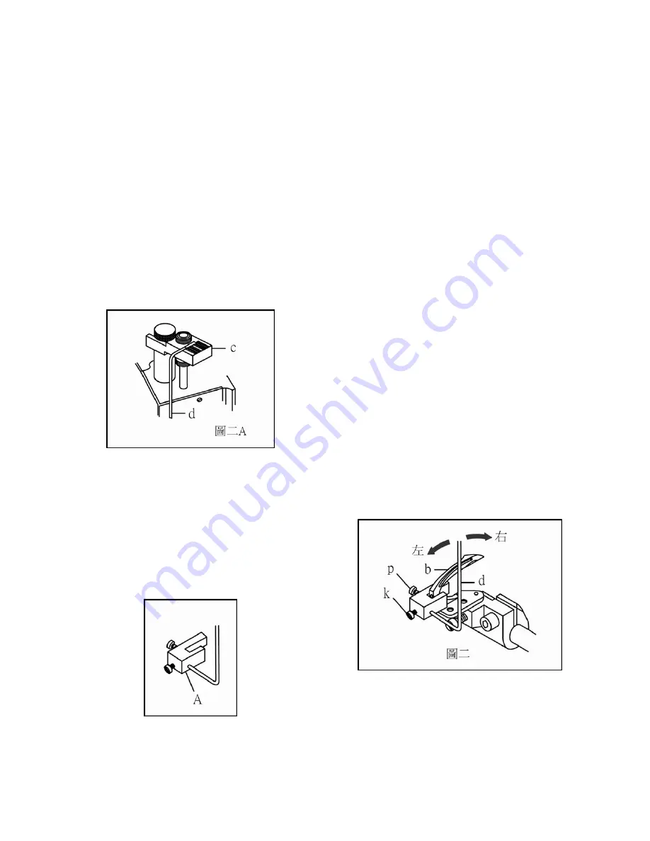
Siruba D007R(B) Original Instructions Manual Download Page 22

-20-


3-6-3   

組裝指針組

A

於下飾線勾針

b

上,將螺

p

鎖緊,同時調整指針

d

的尖端指在刻度量

c

的刻度上,再將螺絲

k

鎖緊,旋轉手輪,

向左擺動當針柱

a

頂到止塊螺絲

h

時,注意指

d

所指示的刻度;當再旋轉手輪,向右擺動

到同樣位置時檢查指針

d

,是否位於前述情形

位於同一個刻度上

  (

圖二

)


3-6-4   

將指針左右擺動於同一刻度上的調整

方法,由前後軸連接襯套

g

鬆開螺絲

e

進行調

  (

圖三

)


刻度量具

c

:零件本校車定規

K13-11


                      (ERP NO.07401311) 

指針組

A

:零件本校車定規

K13-10


                  (ERP NO.07401310) 

指針

d

:零件本校車定規

K13-1


              (ERP NO.07401301)


3-6-3    Please install the measuring gauge 
pointer set “A” on the looper “b” and 

tig

hten it by 

screw ”p”. In the mean

ti

me, please adjust the 

tip


of pointer “d” to the scale of measuring gauge “c” 
and 

tig

hten it by screw ”k”. To turn the 

handwheel and move the pointer “d” to the le

ft


till

 the top of needle bar push the stop screw “h”. 

Please make a noted of the scale of pointer “d”. In 
the other way, to move the pointer “d” to the 
right and make sure it to indicate in the same 
scale or not?? (Fig 2) 

3-6-4    Please loosen the screw “e” on the front 
& rear co

nnecting

 sleeve “g” for adjus

ting

 the 

pointer “d” to locate at same scale. (Fig 3) 

Measuring gauge “c”: K13-11 in spare parts book.
                                  (ERP NO.07401311) 

Measuring gauge pointer set “A”: K13-10 in spare 
parts book. (ERP NO.07401310) 

Pointer “d”: K13-1 in spare parts book.   
                  (ERP NO.07401301) 


Summary of Contents for D007R(B)

Page 1: ...D007R B ORIGINAL INSTRUCTIONS BOOK...

Page 2: ...BETWEEN LOOPER AND NEEDLE PLATE 11 3 3 3 3 THE HEIGHT OF NEEDLE BAR 12 3 4 3 4 THE ADJUSTMENT OF LOOPER MOVED FRONT REAR POSITION 14 3 5 3 5 THE ADJUSTMENT OF LOOPER MOVED RIGHT LEFT POSITION 17 3 6 3...

Page 3: ...machine and must not be used for other purposes 1 1 WORK ENVIRONMENT 1 1 1 Power voltage Only use Power Voltage indicated on the name plate of the HVP 70 10 ranges 1 1 2 Electromagnetic pulse interfe...

Page 4: ...and extension wire when connecting ground wire to Earth and secure it tightly 3 Detailed please consult the motor operation instruction 1 3 SAFETY IN OPERATING 1 3 1 When turn on the machine in the rs...

Page 5: ...when 1 4 1 Uninstall the motor to the control box or plug and unplug any connector 1 4 2 Turn o the power and wait 10 minutes before opening box cover 1 4 3 Raising the machine arms or changing needle...

Page 6: ...hine This symbol indicates dangerous warning which may cause nger eyes injury in careless This symbol indicates electrical risk warning which may cause electric shock in careless This symbol indicates...

Page 7: ...r safety devices Switch o the electric power before threads exchange the needle clear the machine etc Please take care nger eyes when machine be operated The operation way of motor Please connect the...

Page 8: ...6 1 5 3 The location of warning signs...

Page 9: ...the oil is equivalent 2 1 2 Please ll up the oil before the machine be operated Loosen the screw a and ll the oil into the machine in slowly Fig 1 From the plug screw a supply oil until the oil level...

Page 10: ...1 3 H L 2 1 3 Please double check the oil ejective situation in everyday before the machine be operated Fig 3 If the oil level is lower than low line Fig2 H top line L low line please re ll it all the...

Page 11: ...Loosen the screw a b and drain all of old oil from the tank Then tighten the screw a b Fig 4 2 2 2 Please refer to 2 1 2 Fig 1 to re ll the new oil Warning If the oil didn t be exchanged for a long ti...

Page 12: ...older on the looper rocker shaft d Fig 2 3 1 2 Please install looper c on the looper holder d and tighten xed screw e Then to screw on the screw a to hold the looper c Fig 2 Remark Please don t screw...

Page 13: ...close to inside of cylinder bed groove Then moved measuring gauge a to the left and close the looper b Please check the looper is vertical to inside of cylinder bed groove Fig 1 3 2 2 Put on the need...

Page 14: ...ight of longest needle to the needle plate in accordance with needle gauge For example Fig 1 the needle gauge is 4 needle 5 2mm and the correct height is 13 49mm Please loose the screw d to adjust the...

Page 15: ...g to make sure that every needle are passed though the center of the needle hole no the needle plate In the meantime all of needle have to be in parallel and the gap have to be even Measuring gauge c...

Page 16: ...oper avoid lever groove Fig 2 3 4 2 b b d e c b A 3 4 2 To install the measuring gauge b into the hole of front cylinder bed and tight it up by screw c The inner shaft d and plane e of measuring gauge...

Page 17: ...gth of inner shaft d is 2 4mm In the meanwhile the clearance between the big side of inner shaft d and the bushing of measuring gauge b is 0mm Fig 4 Oppositely to move the looper rocker shaft a to the...

Page 18: ...r rocker shaft from the beginning to the end is more or less than 2 4mm Fig 4 Please loosen the screw f Fig 5 to adjust the distance The distance will be decreased when the feed rocker link h is moved...

Page 19: ...c on looper g and close to the scale plate a Turning the handwheel to move the looper g to the right dead point Please adjust the 0 degree of scale plate to the tip of pointer d Then tighten the scal...

Page 20: ...e screw be moved to the right The angle will be increased when the screw be moved to the left Fig 2 Notice The screw e is a left handed thread It s di erent than normal screw Please loosen the screw b...

Page 21: ...ed on the inside of the machine s body which couldn t be touched adjusted That s the reason the screw s has to be loosen rst 3 6 2 To put the measuring gauge c on the presser foot bushing f and tight...

Page 22: ...ve the pointer d to the left till the top of needle bar push the stop screw h Please make a noted of the scale of pointer d In the other way to move the pointer d to the right and make sure it to indi...

Page 23: ...ve the looper a to the left dead point Please lock the needle c into the groove of measuring gauge b The distance between the tip of looper and needle c is 4 76mm Please loosen the screw for adjusting...

Page 24: ...please loosen the screw c and adjusted the clearance via screw d Please note the clearance between the looper a and shortest needle is 0mm Then the clearance between looper a and 2nd needle to 5th ne...

Page 25: ...between 2nd 3rd 4th 5th needle and front needle guard to avoid the collision Fig 2 3 8 3 Please install the rear needle guard h on the xed plate of main feed dog i To turn the handwheel and make sure...

Page 26: ...onnecting bracket Please don t loosen the screw d on the carrier hook sleeve whether assembled or disassembled If the screw d is loosen which will cause a unnecessary clearance at the presser foot lif...

Page 27: ...w t and pass oil pipe tting v Then lock in presser bar w Please tighten screw t Fig 6 and keep the angle between screw t and oil pipe tting v in level Fig 7 Caution Please always keep a clearance betw...

Page 28: ...there isn t any unnecessary clearance Then the presser foot is lifted in smoothly by hand Fig 2 To turn the handwheel and install the adjusting screw a and lock b To tighten the screw c on the connect...

Page 29: ...f long top cover thread carrier p and fake needle B is 0 5mm Please take care that the short long top cover thread carrier can t be hit each other when they be crossed Fig 4 3 9 6 The operated procedu...

Page 30: ...d tighten it by screw b Fig 1 Loosen screw Q and install the lower knife a The tip of lower knife has to aim the center of shortest needle To turn the handwheel and move the moving knife holder F to t...

Page 31: ...de collar e Then please push the upper knife holder h up and insert a 2mm pad between knife holder guide collar e and knife holder shank support f Remark The presser foot couldn t be moved when you pu...

Page 32: ...ted Please avoid the presser bar connecting bracket to hit the machine body Fig 3 and the upper knife holder h hit the knife holder shank support f Fig 2 When the hit is be happen Please loosen the sc...

Page 33: ...1 1 Please follow the procedure A B C to thread Fig 1 3 11 2 The thread have to pass the inside of thread tension disc Fig 2A and the bottom of stitch unlocking spring a when thread the B section Fig...

Page 34: ...read have interlocked with looper thread Please make sure the top cover thread have hooked on the front groove of short top cover thread carrier b Then pull the top cover thread by hand lightly To tur...

Page 35: ...The specification and or appearances of the equipment described in this instruction book parts list are subject to change because of modification which will without previous notice D007R B JUL 2018...

Reviews: