background image


Singer Inspiration 

 27

Setting 

Zero feed

Check

1. Remove the needle.

2. Set the stitch lenght selector at “0” and the pattern selector at 

straight stitch.

3. Place 2 layers of light fabric under the presser foot and lower it.

4. Run the machine at maximum speed. 

5. The fabric should not move in any direction under the presser foot. 

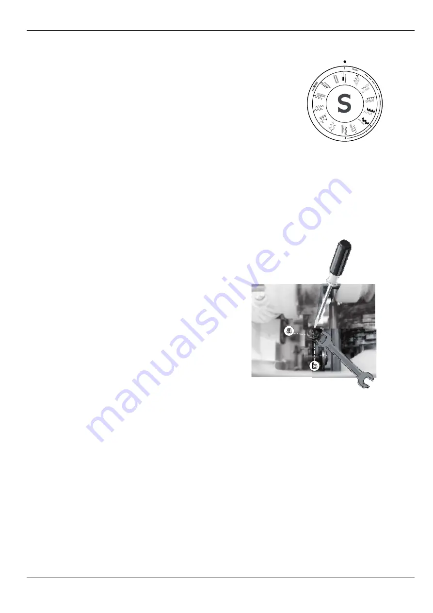
Adjustment

1.Loosen the nut (a) and turn the screw (b) clockwise or counter clockwise until the feeding of 

the fabric stops.

2.Tighten the nut (a).

3. Re-check

Summary of Contents for Inspiration 4205

Page 1: ...Service manual 4228 4220 4212 4206 4210 4205 104 96 22 May 2007 A registered trademark of The Singer company Ltd or its afflliates 2007 Singer Company All Rights Reserved...

Page 2: ...edle 21 Bobbin case position finger 22 Bobbin case position plate 22 Bobbin case clearances 23 Feed rock shaft end play 24 Feed dog centralization 24 Feed dog height 25 Cam controlled feed follower ad...

Page 3: ...Singer Inspiration...

Page 4: ...ents or changes to parts will be made by issuing Singer service parts bulletins Machine Description Tubular bed Lightweight casting Sure fit sewing system Electronic triac foot speed controller New FT...

Page 5: ...can cause poorer results on more normal fabrics How the different standard ratings are set can be seen from the description under each setting instruction The following list of setting gauges and ser...

Page 6: ...e machine Face Cover 2 Lift away the face cover to the front 3 Remove the 6 Philips screws B from the backside of the machine 4 Lay the machine on its back and remove the 3 Philips screws C from the b...

Page 7: ...ush on the cover at these 3 positions 6 Push then the back cover away from the machine Front Cover 7 Remove the stitch dial by pulling it straight out 8 Squeeze the ring in the middle to gether and pu...

Page 8: ...Remove the Tension Dail by pulling it straight out 10 Remove the Presser bar presure knob by pulling it straight out 11 Remove the handle towards the back 12 Remove the 2 Phillips screw G from the bac...

Page 9: ...H from the back of the front cover 14 Remove the Phillips screw I from the back of the front cover located just beside the motor belt 15 Remove the front cover to the front and at the same time remov...

Page 10: ...he gear screw c and lightly move gear e to the left until it just touches the gear d 5 Tighten securely the gear screw c 6 Remove the shim gauge and pull the hand wheel and the horizontal shaft to the...

Page 11: ...gene rated Adjust 1 Loose the pulley screws A and B on the pully C 2 Push down on the vertical shaft e and push up on the pulley C with the cam D tighten the screws A and B 3 Make sure the shaft rotat...

Page 12: ...3 Turn handwheel to bring the needle bar to its lowest position 4 Grasp the needle clamp and check for excessive vertical and radial play by moving needle bar up and down rotatively Adjustment 1 To co...

Page 13: ...he hook point If the point is bent or burred replace the hook 4 Rotate hand wheel until the tip of the hook arrives behind the needle 5 Check the gap by pressing a small screw driver against the needl...

Page 14: ...o Allen screws a and b of the spindle c 3 Turn the spindle to the front or to the back to reach the correct adjustement 3 Tighten the two screws a 4 Recheck and readjust if necessary 5 Check for the d...

Page 15: ...of the bushing b the needle bar height is correct Adjustment 1 If the mark is not aligned with the bottom face of the bushing b loose the screw c a little and push the needle bar up or down to bring...

Page 16: ...the screw a and move the lever b to the left or to the right 2 Tighten the screw a 3 Recheck and readjust if necessary Straight stitch centralizing Check 1 Set the machine to straight stitch 2 Turn th...

Page 17: ...es needle plate slot end Adjustment Adjust the bight stop by moving the thread guide that is located under the face plate 1 Set the stitch width selector to a maximum zig zag position 2 Turn handwheel...

Page 18: ...t may be present NOTE Before any adjustment is done ALWAYS check the needle bar height Adjustment Height 1 Loose the screw c and move the stop d up or down to centralize hook inside the needle eye 2 T...

Page 19: ...3 Tighten the screws a Presser bar height Check When the presser foot is in its highest lifting position it shall be between 7 35 to 7 60 mm above the needle plate Adjustment 1 Raise the presser foot...

Page 20: ...obbin case holder and the bobbin case 2 Rotate the hook back and forth and check the play it should be small as possible Adjustment 1 Loose the screw a and adjust the tensioner so that a weight of 140...

Page 21: ...ush with bottom face of bushing b 3 the point of the hook c should now be in the center of the needle blade Adjustment 1 Turn the handwheel to the front of the machine to so the needle bar comes to it...

Page 22: ...ion plate Check 1 Turn handwheel to the front of the machine to bring hook point to position d 2 Locate the bobbin case so that the left side of its fork is resting against the position finger a 3 The...

Page 23: ...tween retaining plate and bobbin case must be between 0 25 and 0 36 mm NOTE Equaly the clearance between the extension of position plate c and bobbin case up per surface f should comply with the above...

Page 24: ...loose the screw c 5 Move the rock shaft center e to the left against the shaft c 6 Tighten the screw d Feed dog centralization Check 1 Make sure the feed dog is up 2 Set the stitch lenghts to 5 3 The...

Page 25: ...lightelly 3 By means of an open end wrench rotate the eccentric hinge stud b left or right to raise or lower the feed dog NOTE The highest point of eccentric hinge stud c must be to the right before...

Page 26: ...to centralize the follower 3 Tighten the nut a 4 Recheck and readjust if necessary Stitch width selector adjustment 1 Turn handwheel to the front of the machine and observe the maximum movement of zig...

Page 27: ...aight stitch 3 Place 2 layers of light fabric under the presser foot and lower it 4 Run the machine at maximum speed 5 The fabric should not move in any direction under the presser foot Adjustment 1 L...

Page 28: ...a 2 Rotate the eccentric stod to reach the correct condition 3 Tighten the nut a Note This Setting influence the Buttonholer stitch density balance Adjustment 4 step buttonholer 1 Set the pattern sele...

Page 29: ...and reverse adjustment is correct 2 Sew a button hole The Left and right sides of buttonhole must have an equal number of stitches The distance between the two inner perforations should be 0 5 to 1 0...

Page 30: ...lacement of the needle takes place above and out of the paper Adjustment 1 Set the machine on Buttonhole 2 Mount the button hole foot 3 Place a piece of paper on the needle plate and lower the presser...

Page 31: ...adjustment is done adjust if necessary 1 Place a piece of paper on the needle plate and lower the presser foot 2 Turn handwheel and observe the needle penetrations 3 The machine should produce two pe...

Page 32: ...ake a straight stitch sew maximum speed in two layers of light fabric Set the tension at the lateral reference marks a direction 2 In this condition the machine will produce several loops in the back...

Page 33: ...between the retainer plate c and the spring d Adjustment 1 Make a straight stitch sew and observe the thread passing between the spring d and the plate c If the thread does not pass correctly 2 Loose...

Page 34: ...left or right position under spring pressure If the pressure is absent spring will need to be replaced 5 Lift up on bobbin winder tension disc If tension is absent replace the assembly 6 Check for ev...

Page 35: ...g the buttonholer engaging lever backwards a click should be heard Adjustment 1 Loose screw a 2 Push the rod b to the right or to the left 3 Tighten the screw a 4 Make a buttonhole sample in two layer...

Page 36: ...e socket D 3 Disconnect the Lamp cable M 4 Remove the setscrews C and motor G Mount To attach the motor follow the above procedure in re verse Adjusment 1 Slightly loosen the setscrews C 2 While pushi...

Page 37: ...Singer Inspiration 37 Dismantling Removing the Thread tension Unit Removing the Needle bar Bracket...

Page 38: ...38 Singer Inspiration Dismantling Removing the Stitch width selector Removing the Bobbin Winder Mechanism...

Page 39: ...Singer Inspiration 39 Dismantling Removing the Hook and Bobbin mechanism...

Page 40: ...ing of the pores in the bearing surface if such oil or grease are used 3 All thread lint or any foreign matter must be removed before lubrication Caption Singer Oil Silicon type grease 4 Apply to and...

Page 41: ...Singer Inspiration 41 Singer Oil...

Page 42: ......

Reviews: