background image


13 

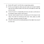
(4)  Set the DIP switch S1 and S2 to the corresponding position. 

(5)  Put  the  wire  through  the  rubber  ring  and  make  sure  the  basic  insulation 

layer and the protective jacket of the wire can put through the rubber ring 

and wire clamp. 

(6)  Connect  the  wire  to  corresponding  terminals,  and  screw  up  the  screw  in 

the contact to make sure that it will not loose. 

(7)  Use  wire clamp to press the wire, and screw up to fix the screws of  wire 

clamp.  If  the  wires  for  connecting  are  less  than  3  sets,  please  use  white 

wire clamp, otherwise use black wire clamp. 

(8)  Close the front cover of dry contact gateway and then tighten the screws of 

the front cover. 

Summary of Contents for DRY CONTACT GATEWAY SDG-01

Page 1: ...DRY CONTACT GATEWAY SDG 01 USER S MANUAL EN ...

Page 2: ... Original instructions IMPORTANT NOTE Read this manual carefully before installing or operating your new air conditioning unit Make sure to save this manual for future reference ...

Page 3: ...of the appliance by a person responsibility for their safety Children should be supervised to ensure that they do not play with the appliance 2 This instruction manual is a universal manual some functions are only applicable to particular product All the illustrations and information in the instruction manual are only for reference and control interface should be subject to actual operation 3 In o...

Page 4: ...unnecessary maintenance violation of related national laws and rules and industrial standard and violation of this instruction manual etc we will bear no liability 5 The final right to interpret for this instruction manual belongs to SINCLAIR CORPORATION Ltd ...

Page 5: ...evel input 5 4 2 2 Impulse input 6 4 3 Output function 7 4 4 Indicator instruction 8 5 Product Installation 9 5 1 Dimension 9 5 2 Installation requirement 10 5 3 Wire specification 10 5 4 Wiring instruction 11 5 4 1 Communication and power cord connection 11 5 4 2 Connection of input dry contact 11 5 4 3 Connection of output dry contact 11 5 4 4 Installation procedure 12 ...

Page 6: ...death to people This sign indicates that the items must be observed Improper operation may cause damage to people or property WARNING This product can t be installed at corrosive inflammable or explosive environment or the place with special requirements such as kitchen Otherwise it will affect the normal operation or shorten the service life of the unit or even cause fire hazard or serious injury...

Page 7: ...2 2 Appearance Fig 2 1 Appearance of dry contact gateway ...

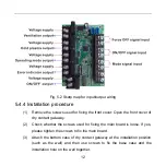
Page 8: ...ce OFF dry contact input terminal block 8 ON OFF dry contact output terminal block 3 ON OFF dry contact input terminal block 9 Error indicator dry contact output terminal block 4 Mode dry contact input terminal block 10 Mode dry contact output terminal block 5 Reserved terminal block 11 Cold plasma dry contact output terminal block 6 DIP switch S2 12 Ventilation dry contact output terminal block ...

Page 9: ...tion definition for DIP switch S1 and S2 please refer to table 3 1 and table 3 2 Table 3 1 Function for DIP switch S1 Dip switch bit 1 2 3 4 5 6 7 Description General terminals control enable Input type Reserved ON position Enable Level Digital position Disable Impulse Table 3 2 Function for DIP switch S2 Dip switch bit 1 2 3 4 5 6 7 Input name Force OFF ON OFF Mode Reserved ON position Enable Ena...

Page 10: ... control the unit 4 2 Input function Dry contact gateway is compatible with level input method and impulse input method which can be selected by the second bit of DIP switch S1 Each input function can be set as enable or disable through the corresponding bit of DIP switch S2 When it is set as disable the unit won t execute corresponding input command The following descriptions of input functions a...

Page 11: ...r impulse input method for each detection of dry contact from disconnected to connected connected time should be more than 500ms it is deemed as valid impulse input When valid impulse input is detected dry contact gateway updates corresponding input commands The detail commands are shown as Table 4 2 For each detection of valid impulse input commands of all the dry contacts will be re executed Whe...

Page 12: ...tput function The dry contact gateway will output corresponding function and status by controlling the connected disconnected of the dry contact User can connect power cord with load to the output terminal to turn corresponding load ON OFF via dry contact gateway Definition of output contacts are shown in Table 4 3 Table 4 3 Function definition of output contact Output dry contact Contact connecte...

Page 13: ... the indicator indicates the normal operation of the dry contact gateway Table 4 4 Indicator instruction No Indicator Function introduction 1 Power indicator red It s on after energization 2 Communication indicator green Flashing during communication ...

Page 14: ...9 5 Product Installation 5 1 Dimension Fig 5 1 Dimension of dry contact gateway unit mm ...

Page 15: ...bedded in the installation hole on the wall Ho line work is not allowed during the complete installation process 5 Please pay attention to below notices for wiring to avoid abnormal phenomenon due to electromagnetic interference 1 Make sure the communication wire connects to the correct interface Otherwise there will be communication error 2 The communication wire of dry contact gateway 4 core wir...

Page 16: ...r unit 5 4 2 Connection of input dry contact Connect two terminals of each group of input dry contact to the both ends of switch respectively Single control switch is suggested for the level input method and touch switch is recommended for impulse input method 5 4 3 Connection of output dry contact Connect the two terminals of each group output to the load respectively The requirement for the allo...

Page 17: ...ront cover of dry contact gateway 2 Check whether the screws used for fixing the main board is loose If yes please tighten the screws to fix the main board 3 Attach the bottom case of dry contact gateway at the installation position such as the wall and then use screws to fix the base case and the installation hole on the wall together ...

Page 18: ...and wire clamp 6 Connect the wire to corresponding terminals and screw up the screw in the contact to make sure that it will not loose 7 Use wire clamp to press the wire and screw up to fix the screws of wire clamp If the wires for connecting are less than 3 sets please use white wire clamp otherwise use black wire clamp 8 Close the front cover of dry contact gateway and then tighten the screws of...

Page 19: ...14 Fig 5 3 Sketch map for wire pressing ...

Page 20: ...d místního úřadu nebo nejbližšího sběrného místa V případě problémů s kvalitou nebo jiných kontaktujte prosím místního prodejce nebo autorizované servisní středisko Tísňové volání telefonní číslo 112 VÝROBCE SINCLAIR CORPORATION Ltd 1 4 Argyll St London W1F 7LD Great Britain www sinclair world com Zařízení bylo vyrobeno v Číně Made in China ZÁSTUPCE SINCLAIR Global Group s r o Purkyňova 45 612 00 ...

Reviews: