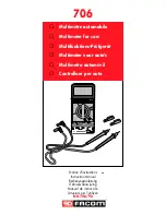
OPERATION
Power
The instrument
is
switched
on by depressing
the power on-off
button
(1).
If
operation from AC line
power
is
required, an
approved
AC
adaptor
(see Note
1
on page 4) may be
plugged
into
the
power
jack
at
the
rear of
the
instrument (2).
Connecting the
AC
adaptor
automatically
increases
the
display
brightness to
maximum.
The instrument may be operated from
disposable
cells (see Note 2
on
page
4) or from
the
optional
rechargeable
battery pack.
Batteries should be fitted into
the
holder housed under
the
slide-
off cover (3), care being taken to observe polarity.
It is
essential
that the disposable/rechargeable selector switch
(4)
is
positioned
correctly before
connecting the
AC
adaptor/charger.
Function
and Range
Selection
The Function and Range are
selected
by
the push-buttons
(5) and
(6)--
DC
:.
volts:
6
ranges are available covering
voltages
up to
1200 volts. The input
is
applied
between
terminals (8) and (7). The 2000mV ultra high
impedance
range
is
selected
by
simultaneous
depression of
the
V
and
mA
buttons
and
a
release of
all
the
range
buttons
(half depression
allows release). DM450 will read
in
21—2),
AC~
volts:
5
ranges are available for inputs up to 750 volts
rms
connected
to terminals (8) and (7). The
instrument
senses the
mean value of
the
input
signal and
is
calibrated to read
the
rms value of
a
sine wave.
A DC
level on
the
AC
signal
will
not affect
the accuracy
of
the
AC
reading pro-
vided
that
DC
level plus AC rms level
does
not
exceed
the
maximum reading of
the
range.
DM450 displays only
3%
digits on 200mV.
DC:
Current:
8
ranges
are available for inputs up to 10A
continuous
(20A
intermittent).
Connect
to
terminals (8) and (7)
except
10A which
is
to
(9) and (7). 20pA and 29A
ranges
are available
by
depressing
V
and
mA
function
buttons
simultaneously
—
this gives a
[LA/10
function
which can be used with
the 200
or 20
range
buttons.
AC~ Current:
As for DC current. Sensing information as for
AC
volts. DM450 displays only 3‘7digits.
Resistance:
6
ranges
are available for
resistances
up to
20M
9. Connect between
terminals (8) and
(7)-
Diode
Test:
Select 2K9. Connect diode across
terminals
(8) and (7) with
anode
to common
(7).
Forward
voltage
drop
is
displayed
in
volts.
Overrangelndication
DM350:
When
a
reading of 1999
is
exceeded,
overrange
is
in-
dicated by blanking of
all
but
the
most significant digit
which
is
displayed as
a
1
with
a
negative sign
if
appropriate.
DM450:
When
a
reading of
19999
is
exceeded,
overrange
is
indicated by
a
reading of
$0000
and flashing of
the
whole
display.
When overrange indication occurs,
the
next
highest
range should be
selected.
Input
Terminal
Polarity
The negative (common) terminal (7)
is
the
low potential terminal
with
respect
to ground.
If
the
positive terminal
is
taken negative
with
respect to the
common terminal,
a
negative sign will be
automatically
displayed.
When
measuring
AC~
signals, or
DC..—.
signals with
AC~ superimposed
on' them,
the
common
terminal should be
connected
to
the ground
side of
the
signal
being
measured
regardless of
the
actual polarity.


