background image

Description 

sinaCAM 

Rev.: 1.2 (A) 

Quick Start Guide 

6.2.1


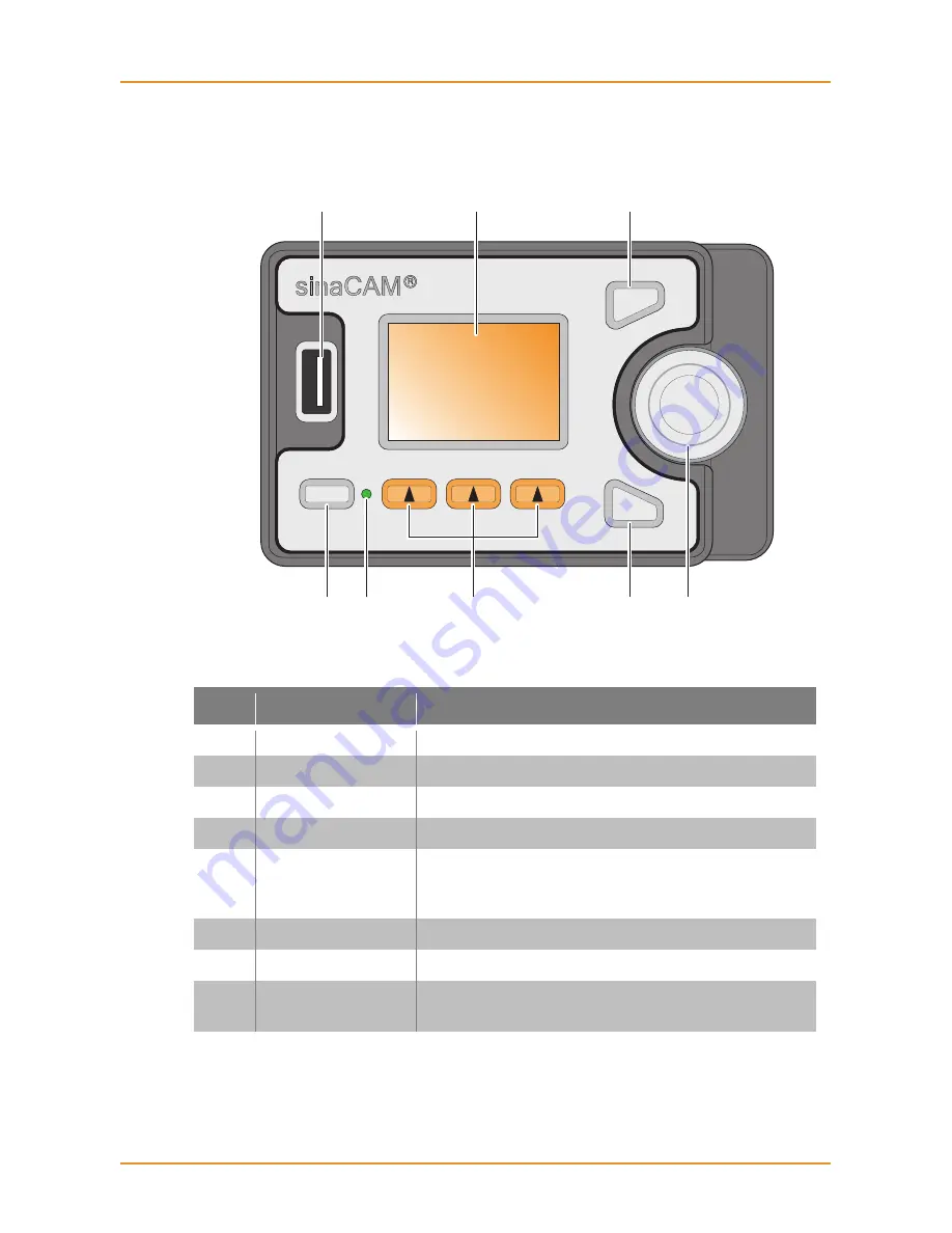
The Control Panel 

Figure 3: 


The Control Panel 


Table 4: 


Controls and their Functions 

Item 

Designation 

Description 

USB 2.0 port 

Enables frame grabs to USB sticks 

Display 

Graphical user interface display 

F1 button 

To select a menu item as displayed 

Power switch 

Turns power ON or OFF 

Power LED 

Glows red when the unit is connected to the 
power supply, and glows green when the unit 
is powered on 

Arrow buttons 

To select a menu item as displayed 

F2 button 

To select a menu item as displayed 

Scroll wheel 

Scroll wheel and pushing button to navigate 
through the menus and select options 


POWER

F1

F2

B

C

G

D

E

H

F

A

Summary of Contents for HDC1-D

Page 1: ...1 2 A...

Page 2: ...ble protection against harmful interference in a residential installation This equipment generates uses and can radiate radio frequency energy and if not installed and used in accordance with the inst...

Page 3: ...d anadicon solutions All rights reserved All text graphics design and other works contained herein are copyrighted works of Solectrix Systems and anadicon solutions Any redistribution or re production...

Page 4: ...o not open the housing or attempt to repair or modify any part of the camera system Repairs must only be carried out by authorized sinaCAM service centers Do not store the camera system near a strong...

Page 5: ...es for the environ ment and human health At the end of its lifespan take the product to an appropriate recycling station For more information about correct disposal of electrical and electronic equipm...

Page 6: ...e back distance adjustment ring rotates independently of C mount and lens C Lens mount Standard C mount thread D Lens mount lock Allows for lens scale position alignment in 30 steps E System LED Glows...

Page 7: ...points M4 thread for attaching a handle or to fix the base unit to a mounting plate C System battery compartment The system battery supplies power to the inter nal clock only It does not supply the ca...

Page 8: ...r interface display C F1 button To select a menu item as displayed D Power switch Turns power ON or OFF E Power LED Glows red when the unit is connected to the power supply and glows green when the un...

Page 9: ...rator C HD SDI output 1A 1B Terminals for e g a HD SDI monitor a recording device or a 2D 3D converter 1A 1B provides the image signal coming from remote head terminal 1 D HD SDI output 2A 2B For the...

Page 10: ...Supply It is recommended to only use official sinaCAM accessories as a power supply For official sinaCAM accessories please refer to www sinacam eu CAUTION The use of a wrong power supply can cause f...

Page 11: ...re 6 Advanced Dual Link Setup Figure 7 Broadcast Setup REC REC 3D Recorder 3D 3D Monitor Monitor 3D Monitor DC IN 12 24V EVF Electronic View Finder Dual Link Recorder Dual Link Recorder DL REC DL REC...

Page 12: ...WBalance Gamma CM 50i FULL ASA 200 USER R709LEG MAN AWB BACK 0 99 to 99 WB ADJUST Red level Head1 2 Blue level Head1 2 0 0 0 BACK HOME FPS Shutter Gain WBalance Gamma CM 50i FULL ASA 200 5600K R709LEG...

Page 13: ...continuously Note The system LED of the remote head can indicate additional status in formation For more indications refer to sinaCAM s detailed user manual Switching OFF Push and hold the power switc...

Page 14: ...with Gepco VHD1100 Cable Option Lens Mount C mount with Flange Back Distance adjustment Power Consumption 4 6 W max Operating Temperature Range 0 to 45 C 32 to 113 F Base Unit HDC1 200 Digital Signal...

Page 15: ...24p 25p 30p 50p 60p 23 98p 29 97p 59 94p 3D Monitoring CAM1 CAM2 Alternate Frame Alternate Line Subtract Anaglyph Synchronization Internal or GenLock to Tri Level Sync or Black Burst Communication Por...

Page 16: ......

Reviews: