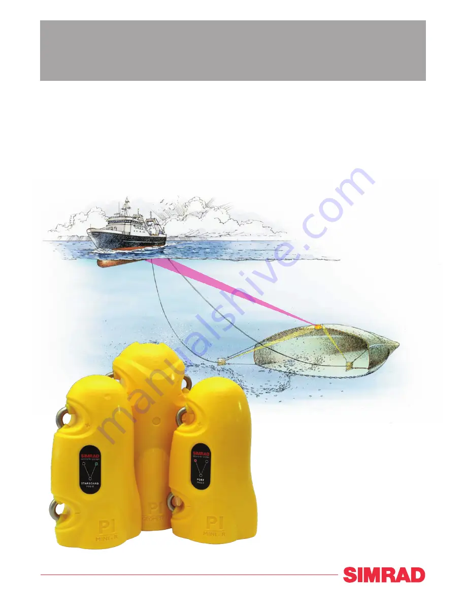
Instruction manual
Simrad PI GeometrySensor system for trawl and danish seine
T E C H N O L O G Y F O R S U S T A I N A B L E F I S H E R I E S
www.simrad.com
(CD012221-002)
Page 1: ...Instruction manual Simrad PI Geometry Sensor system for trawl and danish seine T E C H N O L O G Y F O R S U S T A I N A B L E F I S H E R I E S www simrad com CD012221 002 ...
Page 2: ......
Page 3: ... gives you the necessary information for mounting charging and maintaining the PI Geometry sensor It also explains how to set up the PI44 and PI54 catch monitoring systems to receive and display the information provided by the sensor 322482 B 13 02 2009 ...
Page 4: ...r omissions Warning The equipment to which this manual applies must only be used for the purpose for which it was designed Improper use or maintenance may cause damage to the equipment and or injury to personnel The user must be familiar with the contents of the appropriate manuals before attempting to install operate or work on the equipment Kongsberg Maritime AS disclaims any responsibility for ...
Page 5: ...Basic configuration 17 Configuration of the PI32 18 Configuration of the PI44 and PI54 18 About sensor configuration 20 Default communication channels and update rates 20 Changing a communication channel 20 Changing the update rate 21 PI Configurator 22 DISPLAY PRESENTATIONS 23 Numerical presentation 23 Graphic presentation on PI32 24 Graphic presentation on PI44 and PI54 24 CHARGING AND MAINTENAN...
Page 6: ...Simrad PI Geometry PI MiniCharger indicators 34 How to use the Simrad PI MaxiCharger 34 Daily operation of the PI MaxiCharger 35 PI MaxiCharger indicators 36 4 322482 B ...
Page 7: ... been developed to be used on both bottom and pelagic trawls as well as pair trawls and danish seiners In addition to the PI Geometry sensor the system uses two PI Mini R transponders These are mounted on the trawl doors or trawl wings Note Two PI Geometry sensor configurations are available the standard type and the XT The standard PI Geometry configuration is used when the distance between the P...
Page 8: ...ensor uses an acoustic link to transmit the results from the distance measurements to the PI system on the vessel Two sets of PI Geometry sensors with corresponding Mini R responders can be used simultaneously Note Each PI Geometry sensor can be set up to communicate with one of two sets of Mini R responders number 1 and 3 or number 2 and 4 Make sure that the PI Geometry sensor is labelled accordi...
Page 9: ...sensor main parts identification A Negative charging and fastening lug B Positive charging and fastening lug C Communication link to the vessel and to the responders D Geometry set identification E Location of water switch and sensor identification label 322482 B 7 ...
Page 10: ...t from time to time to remove corrosion or replace it if necessary The Simrad Mini R responder Each PI Geometry sensor needs two Mini R responders one on each trawl door or wing The two responders must be installed with the exact same distances from the PI Geometry sensor The communication transducer next to the identification label on each responder must point towards the PI Geometry sensor on th...
Page 11: ...sponder main parts identification A Negative charging and fastening lug B Positive charging and fastening lug C Communication link to the PI Geometry sensor D Responder identification port or starboard E Location of water switch and sensor identification label 322482 B 9 ...
Page 12: ...remove corrosion or replace it if necessary E Transducer for communication with the PI Geometry sensor Why use the PI Geometry sensor system In order to maximize the performance and the catch efficiency the trawl and the warps must be adjusted properly This is essential to ensure a square trawl and minimum skew This is also important for danish seines as the ropes must have identical length Any di...
Page 13: ...n the port side is longer than distance B on the starboard side The trawl is unbalanced On the right trawl the distances are identical Measuring the door spread C will not detect a distorted trawl geometry If the rigging of the trawl is correct you can easily compensate for skew by adjusting either port or starboard wire length The PI Geometry sensor system is based on the fact that a correct rigg...
Page 14: ...o correct the trawl geometry by adjusting the warp lengths Danish seine Detects variations in the distance from the centre of the headrope or footrope to either wing of the seine Detects differences in the rope lengths when the seine is closed distances between the wings should then be close to zero 12 322482 B ...
Page 15: ... they will communicate with the PI Geometry sensor PI Geometry sensor installation The PI Geometry sensor must be mounted at the exact centre of the trawl or danish seine opening The most common location is at the headrope at the top of the opening It may however also be place at the footrope Note Ensure that you mount the sensor with the transducer opening facing forward There must be a clear lin...
Page 16: ... fastening lugs A on the sensor using two snap hooks and rope 4 Secure the two aft fastening lugs B on the sensor using snap hooks and strong rubber bands This mounting places the sensor in a cradle supported on all four sides 5 Ensure that the sensor is properly mounted Check that it is not permitted to move sideways during the fishing operation as this may lead to a communication failure 6 Make ...
Page 17: ...ngle of attack 37 degrees is approximately 15 degrees You must however adjust this angle depending on the length of the chains between the trawl door and the trawl and the operational properties of the trawl door If in doubt consult the trawl door manufacturer The two rubber inserts provided at the bottom of each sensor adapter must not be replaced with any other types or designs It is essential t...
Page 18: ...top of the trawl opening or behind the footrope at the bottom B The two Mini R responders are normally mounted in dedicated adapters on the two trawl doors They may also be mounted on the trawl wings C Communication links between the PI Geometry sensor and two Mini R responders D Communication link between the PI Geometry sensor and the PI hydrophone below the vessel hull 16 322482 B ...
Page 19: ... use the PI Configurator utility See PI Configurator on page 22 Basic configuration Basic settings When you put the PI Geometry to use you must set it up with one unique sensor number with two measurements Only one update rate can be chosen this is common for both measurements The channel numbers are defined individually for the two measurements Both the update rate and the channel numbers must be...
Page 20: ...by the PI Geometry sensor For more detailed information about the settings and parameters refer to the relevant operator and or reference manual s Note In order to set up the PI44 and PI54 systems your PI operator unit must be provided with MMI software version 0 50 or later and digital signal processor DSP software version 1 11 or later If in doubt check your software versions on the Status displ...
Page 21: ...warning How to set up the geometry readings 1 To reset the unit set all six sensors to default sensor type None 2 Choose the sensor input you wish to use for the PI Geometry sensor 1 to 6 3 Define the sensor type by default None to Dual 4 Set Update to the correct update rate 5 Set Measure 1 to the chosen sensor type Geometry 0 to 300 m or Geometry XT 0 to 600 m 6 Set the communication Channel to ...
Page 22: ...el s Update rate PI Bottom Contact 6 Normal PI Catch 4 Normal PI Depth Depth 300M 16 Depth 600M 12 Depth 1000M 10 Fast PI Height 14 Fast PI Remote Depth Depth 300M 11 Depth 600M 15 Depth 1000M 13 Fast PI Spread 2 Fast PI Spread Depth Depth 300M 16 Depth 600M 12 Depth 1000M 10 Spread 2 Fast PI Twin Spread 2 and 7 Fast PI Temperature 8 Fast PI Geometry 1 and 5 Fast PI SeineSounder Depth 300M 5 Depth...
Page 23: ...els use lower transmission frequencies All sensors are provided from Simrad with a default communication channel In some cases you may find that the chosen channel does not suit your operational needs for example if you have more than one sensor of any given type This is a decision you have to make depending on how many sensors you use and how many of these that are identical Changing the update r...
Page 24: ...y to change the sensor configurations By means of an ordinary desktop computer and a few special cables you can do this job yourself If you do not require frequent configurations you can also contact you local dealer for assistance Contact your dealer for more information 22 322482 B ...
Page 25: ...tation example 1 X1 m 143 5 q 1 X2 m 143 5 q CD012221 007 A B C I E D F H G 1 1 A Sensor identification B Unit of measurement C Distance D Distance changes per minute E Arrows pointing out means that the distance is increasing arrows pointing in means that distance is decreasing F Visual alarm G Sensor transmission indicator H Interference warning I Dual sensor identification On the PI display you...
Page 26: ...e Mini R responders are mounted Figure 11 Graphic presentation on PI44 PI54 17 5 12 5 10 7 5 5 2 5 15 min 38kHz 1000W MEDIUM T 22 5 C o S 7 2kn DK 1050 m CD012106 001 S1 m X2 m 69 5 147 0 0 5 2 X3 m 147 0 0 50 100 150 200 250 0 5 This example shows a graphic display with PI Spread and PI Geometry sensors connected The top line shows the distance between the trawl doors It is currently 69 5 meters ...
Page 27: ...alue into the Delay column This function is not important when you use the PI Geometry sensor We recommend that you choose the default value 7 Enter requested value for Width Use this parameter to control the thickness in pixels of the marker line s 8 For every marker line set Show to On 9 If you wish to see the marker lines in the expanded views bottom expansion zoom and phased range set Sensor m...
Page 28: ...nd locate the Trawl info menu 2 Set Clump sensor to Geometry 1 3 Set Door sensor to Geometry 2 4 Set Trawl data in additional window to On 5 Set Type of trawl data to Spread 6 Press the ENT button to save the chosen parameters and return to the graphical presentation 26 322482 B ...
Page 29: ...h a water switch and two different types are used If your sensor is equipped with a sacrificial brass screw observe the following procedure for replacement 1 Turn the sensor upside down and locate the brass screw 2 Inspect the screw for wear and tear 3 If the head of the screw is corroded try to remove this with a sharp object to achieve maximum electrical contact with the sea water 4 If replaceme...
Page 30: ...h and two different types are used If your sensor is equipped with a sacrificial brass screw observe the following procedure for replacement 1 Turn the sensor upside down and locate the brass screw 2 Inspect the screw for wear and tear 3 If the head of the screw is corroded try to remove this with a sharp object to achieve maximum electrical contact with the sea water 4 If replacement is required ...
Page 31: ...recommended Optimal sensor charging temperature is from 10 to 25 C Note Charging sensors at sub zero temperatures can create explosive gasses Kongsberg Maritime AS assumes no liability for improper charging of sensors or the use of chargers not specified in our sensor or charger documentation PI Mini R charging The PI Mini R responder must be charged between operation The battery lifetime depends ...
Page 32: ...ger is an intelligent battery charger for fast and secure charging of all PS and PI sensors The charger will automatically set up the correct charging current depending on the sensor type and the battery temperature A fuel meter shows the status of the battery during the charge Figure 12 The PI Charger set up to charge a PI sensor Even though the PI Charger is designed for fast charging of the PI ...
Page 33: ... The temperature is shown on the thermometer on the charger s front panel If you charge a sensor that can not be fast charged this thermometer does not work 4 Observe the charge times and temperature limitations Fast charge The PI Charger will first recharge the sensor battery for approximately one hour to reach 70 battery capacity then approximately three hours to reach 100 capacity Once fully ch...
Page 34: ...ging of PI sensors Green Battery temperature between 5 and 40 C Fast charge is enabled Green and Blue Battery temperature between 0 and 5 C Fast charge is disabled normal charge is used Green and Red Battery temperature between 40 and 50 C Fast charge disabled normal charge is used Blue Battery temperature is below 0 C No charging takes place Red Battery temperature is above 50 C No charging takes...
Page 35: ...arging or the use of other chargers than those approved by us Figure 13 Simrad PI MiniCharger Caution The Simrad PI MiniCharger is designed to charge the S Type sensors You may charge the L Type sensors too but due to the small charge current this will not be efficient The Simrad PI MiniCharger is provided with a small booklet from the manufacturer Mascot Read this booklet before you put the charg...
Page 36: ...This means that top charging is in progress When the battery is fully charged the lamp turns steady green Trickle charging is now active You can safely allow trickle charging for long periods of time PI MiniCharger indicators The charger is only equipped with a single indicator lamp this lamp will however change colour to show the status of the charging process Yellow The charger is connected to 2...
Page 37: ...for improper charging or the use of other chargers than those approved by us Daily operation of the PI MaxiCharger 1 Connect the charger to 230 Vac and check that the charger lamp is lit in yellow 2 Ensure that mounting materials do not short circuit the charging lugs This may be ropes wires chains or other items that obstruct or short circuit the electrical connections 3 Attach the charging clamp...
Page 38: ...steady green Trickle charging is now active You can safely allow trickle charging for long periods of time PI MaxiCharger indicators The charger is only equipped with a single indicator lamp this lamp will however change colour to show the status of the charging process Yellow The charger is connected to 230 Vac it has not been connected to the sensor and it is ready for use Orange Red The charger...
Page 39: ...sponder 9 Maintenance 27 PI Geometry 27 PI Mini R 28 Mini R main parts 9 responder 8 Modifying communication channels 20 update rate 21 N Numerical presentation 23 P Parts identification 7 Mini R responder 9 PI Charger use 30 PI Configurator description 22 PI Geometry purpose 5 PI Geometry sensor why use 10 PI MaxiCharger use 34 PI MiniCharger use 33 PI32 configuration 18 graphical presentation 24...
Page 40: ...aritime AS Kon g s b e rg M a rit im e A S S t ra n d p rom e n a d e n 5 0 P O Box 1 1 1 N 3 1 9 1 H ort e n N orwa y S im r a d Te le p h on e 4 7 3 3 0 3 4 0 0 0 Te le fa x 4 7 3 3 0 4 2 9 8 7 con t a ct s im ra d com w w w s im r a d c o m ...