background image

CP33 Pilot menu & navigation examples 

Chapter 6-5

6.2.2 Navigation setup

If you wish to make any changes in the navigation setup, you can 
quickly enter the navigation setup display by pressing [ENT] from 
the highway display (graphical steering display).

ENT


Quick access to navigation setup from active highway display, or...

-refer to display example and description of functions in section 6.1.

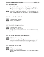
6.2.3 Pilot mode - Turn NAV off

MENU


Call up the menu bar, and...

4,2


turn off navigation mode

6.2.4 Pilot mode - Waypoint advance

MENU


Call up the menu bar, and...

4,3


activate shift to next waypoint

-it will require that navigation mode is active and that “a next way-
point” exists.

6.2.5 Pilot mode - Restart to approaching point

MENU


Call up the menu bar, and...

4,4


activate restart to approaching point

-if you for some reason have drifted off course and wish to restart 
navigation from your actual position to the approaching point.

6.2.6 Pilot mode - ETA & AVN

MENU


Call up the menu bar, and...

4,5


load the ETA & AVN display

-it will require that navigation mode is active - see display example 
next page.

Summary of Contents for CP33

Page 1: ... CHART menu or when unit is off All electronic navigation equipment is subject to external factors beyond the control of the manufacturer Therefore such equipment must be regarded as an aid to navigation The prudent navigator will for that reason never rely on a single source for position fixing and navigation ...

Page 2: ...urrent speed course bearing distance to MOB position and current depth PAGE MOB Page 2 The Chart 2 display will appear with the same type of information as MOB Page 1 PAGE MOB Page 3 Data display will provide information of Course Bearing and Distance to MOB position time elapsed since the incident occured first in seconds and then in minutes if is shown instead of numbers of minutes means that th...

Page 3: ...ff 2 8 Chapter 3 Chart menu and INFO windows 3 Chart menu 3 1 3 1 Charts 3 1 3 1 1 Data field in chart 3 2 3 1 2 Ship symbol 3 2 3 1 3 Cursor function 3 3 3 1 4 Range or zoom function 3 3 3 2 C MAP cartridge 3 5 3 3 INFO windows 3 7 3 3 1 Cursor inactive 3 7 3 3 2 Cursor active but not placed on any object or data 3 8 3 3 3 Cursor placed on waypoint 3 9 3 3 4 Cursor placed on route leg or line sec...

Page 4: ...s stored in the memory 5 12 5 6 1 Delete tracks via menu 5 13 5 7 Targets stored in the memory 5 14 5 7 1 Delete target via menu 5 15 Chapter 6 Pilot menu navigation examples 6 Pilot menu with NAV inactive 6 1 6 1 Highway display 6 1 6 2 Pilot menu with NAV active 6 3 6 2 1 Highway display 6 4 6 2 2 Navigation setup 6 5 6 2 3 Pilot mode Turn NAV off 6 5 6 2 4 Pilot mode Waypoint advance 6 5 6 2 5 ...

Page 5: ... output 9 8 9 4 Decca lanes 9 9 9 5 Loran C 9 10 9 6 Display color 9 11 9 7 Factory settings 9 13 Chapter 10 Installation and service 10 Installation and service 10 1 10 1 Installation notes 10 1 10 2 Installation of CP33 Chartplotter 10 3 10 3 Location for display unit 10 4 10 4 Installation of DS33 Dual Station 10 5 10 4 1 Operation of DS33 Dual Station 10 5 10 5 Installation of antenna 10 6 10 ...

Page 6: ...of contents CP33 Chartplotter Appendix A Glossary of terms A 1 Appendix B List of datum B 1 Appendix C C MAP attributes C 1 Index Declarations of conformity International warranty List of Simrad distributors ...

Page 7: ... in order to provide an accurate and reliable service which include a 24 hour global coverage The GPS system consists of approx 24 satellites which orbit around the Earth at an altitude of approx 20 200 km The satellites transmit perfectly synchronized data However depending on the position the signals will reach the receiver at a slightly different time By adding the measured time difference to t...

Page 8: ...n italic next to the key 1 2 Safety summary Precaution Do not open the equipment only qualified persons should work inside the equipment If the glass in the screen breaks be carefull not to get cut on the sharp edges of the glass pieces Power source fuse and power cable Check that the DC power supplied to the unit is within the range of 10 to 32 volts Note that the appropriate fuse must be employe...

Page 9: ...dated within a few minutes When ready the ship symbol on the chart will flash and the will be replaced by actual course and speed figures 1 3 1 Dedicated function keys Press the CHART key to toggle between CHART 2 sec Chart 2 Chart 2 data field Chart 1 The ECHO key is a shortcut to ECHO Depth temperature diagram Press the PILOT key to toggle between PILOT Highway ETA AVN Trim highway PAGE Press th...

Page 10: ...call up a small data window with details on the object The data window will stay on screen for about 10 seconds or till cursor is moved Press ENT 2 to access further details on C MAP objects or user data i e waypoints routes etc Press CLR to switch off cursor function The ship symbol will now automat ically home and stay on screen Find nearest tide station and port services 1 Press cursor key to a...

Page 11: ...ress PLOT repeat 4 Press ENT when ready to save the route You can enter a new name for the route change type and color for the course line 5 Press ENT to accept and save the route How to make a route from existing waypoints stored in the WP list 1 Press MENU 3 2 to call up the route list 2 Press CLR Make new route from WP list 3 Move cursor up down to select the WP position for the first routepoin...

Page 12: ...GOTO 2 2 Press ENT to start navigation Without placing cursor on the symbol of the WP you wish to go to 1 Press GOTO 2 2 Use the keys to select the WP you wish to go to 3 Press ENT to start navigation How to start route navigation two ways Place cursor on the routepoint you wish to go to first 1 Press GOTO 3 2 Select direction in route Forward or Reverse 3 Press ENT to start navigation Without pla...

Page 13: ...ce to next point in the route Press GOTO 3 to stop navigation Start and stop track 1 Press MENU 3 5 2 Before tracking is started you can give the track a new name make changes to track interval track line type and color 3 Press ENT to start track 4 When you wish to stop tracking press MENU 3 6 ENT ...

Page 14: ...Chapter 1 8 CP33 Introduction and safety summary ...

Page 15: ...splay and page system The CP33 Chartplotter has a multi function screen and data presen tation system with full screen or a split screen with chart and data Full screen Split screen There are four preset pages which can be set up to the presentation you prefer see next page ...

Page 16: ... the 4 pages in intervals of 5 seconds this interval can be changed refer to section 9 1 Press PAGE again to return to normal operation Example of how to change a pre set page For instance if you are in the process of making a track you may want to exchange the Highway display with the Tracking display PAGE Press the PAGE key until the Highway display appears MENU Call up the menu bar and 3 7 then...

Page 17: ... screen data displays MENU Turns the menu bar on off Exits any data display without taking any action ENT Opens for confirms insertion and editing of data Calls up informa tion on marks waypoints etc on chart together with several INFO windows from a chart display Gives access to setup displays Moves cursor in data displays and charts activates cursor on chart Moves left right up down in the menu ...

Page 18: ...reen some of the menus have been abbreviated However the last selected menu will be high lighted and if it s an abbreviation of the menu then the complete menu title is written above the menu bar PILOT 1 CHART 2 POS 3 WP RTE 4 PILOT 5 ECHO 6 MISC 7 SETUP 1 Highway 2 Waypoint navigation etc Having selected e g 4 PILOT from the menu bar its associated menus will drop down Key in the number next to t...

Page 19: ...rt 2 1 6600000 2 Dual speed 2 Routes 3 C MAP cartridge 3 Speed course depth 3 Route calculation 4 Speed diagram 4 Lines 5 Satellites 5 Start track 6 DGPS 6 Stop track 7 SDGPS 7 Tracks 8 Targets 4 PILOT 5 ECHO 6 MISC 1 Highway 1 Depth temperature diagram 1 Wind 2 Waypoint navigation 2 MOB position 3 Route navigation 3 DSC alarm 4 Track navigation 4 Data transfer 5 Anchor guard 6 Trim highway 7 Set ...

Page 20: ...hen selecting a sub menu in the SETUP menu the display will always appear in a pop up window so once you have accepted the changes or decide to just exit the display then the display will disappear from the screen It will not stay on as part of the page system as you have no use for this type of display in the page system 1 Speed alarm units language 2 NMEA interface 3 Alarm output 4 Decca lanes 5...

Page 21: ... back one space if you make a mistake Depending on the selected language the 0 zero key will hold special charac ters e g Æ Ø Å Ä Ö Ü Ñ and the 9 nine key will hold empty space Press the CLR key to delete everything from cursor position and to the right of cursor in that row 2 7 Initial start up PWR To turn on the CP33 press and hold the PWR key till a picture appears on the screen ENT Press ENT t...

Page 22: ...U Call up the menu bar and 7 1 press 7 1 to call up the language display Press up on the cursor to go to the bottom line in the display Select language ENT Confirm entry 2 8 Turn power off PWR Call up INFO window and PWR Press and hold until screen turns black The CP33 is now turned off All the data and setups are saved and stored in the internal memory and of course will be available next time th...

Page 23: ...nd 2 to call up Chart 2 The chart display opens for the built in world chart as well as the optional detailed C MAP electronic chart system which of course will require that a C MAP NT C card is inserted in the drawer below the keypad CHART Hotkey to chart functions 1 Jumps to page with Chart 1 if present in the page system 2 Jumps to page with Chart 2 if Chart 1 is not in the page system 3 Insert...

Page 24: ...tor and accuracy With cursor on the data field will give you the ship s current speed and course the cursor position in lat long bearing and distance from actual posi tion to cursor position 3 1 2 Ship symbol The ship symbol indicates the present position on the chart and the vector informs of the actual true course course over ground There is a built in autohome function which automatically moves...

Page 25: ...ays the cursor will be shown in form of either a ruling box around the active field or the active field will be highlighted 3 1 4 Range or zoom function With chart display active 1 9 Press one of the numeric keys to quickly change the chart scale 1 1 600 2 1 2 000 3 1 6 000 4 1 20 000 5 1 60 000 6 1 200 000 7 1 600 000 8 1 2 000 000 9 1 6 600 000 Press the minus key to zoom in for details smaller ...

Page 26: ... blue white with coordinate grid when Grid is set to AUTO default in chart setup depending on the actual scale see section 3 4 Chart setup for more details in regard to what can be shown on the chart and what you may choose not to have shown The built in world chart can be zoomed up down in six steps from a scale of approx 1 33 000 000 to 1 2 000 000 An over zoom function enables you to zoom beyon...

Page 27: ...op up window for C MAP cartridge which also brings the chart system in stand by To open the drawer below the keypad press the eject key next to the drawer Place the cartridge in the tray with the terminals pointing towards the unit and push the drawer back in place make sure it is closed tight so it remains watertight ENT Press ENT to test the data on the C MAP C card The unit will now test the da...

Page 28: ...reas can be turned off so they will not be visible on the chart refer to section 3 4 Chart setup Other chart areas can quickly be reached by means of the zoom keys Zoom out until desired area becomes visible Move cursor to approximate area and Zoom in The chart will automatically start to move when cursor reaches the edge of the screen When cursor is switched off CLR the chart will return to ship ...

Page 29: ...th the following to choose from text in red are inactive functions Scale 1 6600000 Actual chart scale No user data at ship s position 1 Edit user data Inactive function 2 Chart info Refer to Appendix C 3 Find nearest port services Refer to Appendix C 4 Bearing and dist from A to B Inactive function 9 Chart setup Refer to section 3 4 0 Ship to center PAGE More user data MENU Exit Exit info window 0...

Page 30: ...ive function 2 Chart info Refer to Appendix C 3 Find nearest port services Refer to Appendix C 4 Bearing and dist from A to B 9 Chart setup Refer to section 3 4 0 Cursor to center PAGE More user data Inactive function MENU Exit Exit info window 4 Bearing dist from A to B will quickly provide the bearing and distance from your current cursor position A to an arbitrary point B Move cursor to point B...

Page 31: ...2 Chart info Refer to Appendix C 3 Find nearest port services Refer to Appendix C 4 Bearing and dist from A to B Refer to section 3 3 2 9 Chart setup Refer to section 3 4 0 Cursor to center Refer to section 3 3 2 PAGE More user data MENU Exit Exit info window 1 Edit user data opens for a new info window Waypoint 1 Edit Edit name symbol color etc 2 Move Move waypoint with cursor CLR Delete Delete w...

Page 32: ...ix C 3 Find nearest port services Refer to Appendix C 4 Bearing and dist from A to B Refer to section 3 3 2 9 Chart setup Refer to section 3 4 0 Cursor to center Refer to section 3 3 2 PAGE More user data MENU Exit Exit info window 1 Edit user data opens for a new info window Route leg 1 Edit leg Open new info window to edit route leg 2 Insert point Move cursor to insert new point 3 Edit Open new ...

Page 33: ...ppendix C 4 Bearing and dist from A to B Refer to section 3 3 2 9 Chart setup Refer to section 3 4 0 Cursor to center Refer to section 3 3 2 PAGE More user data MENU Exit Exit info window 1 Edit user data opens for a new info window Routepoint 1 Edit point Open new info window to edit routepoint 2 Move point Move point with cursor CLR Delete point Delete routepoint 3 Add point Add point to route i...

Page 34: ...4 Bearing and dist from A to B Refer to section 3 3 2 9 Chart setup Refer to section 3 4 0 Cursor to center Refer to section 3 3 2 PAGE More user data MENU Exit Exit info window 1 Edit user data opens for a new info window Trackpoint CLR Delete point Delete trackpoint 1 Delete points from A to B See below 2 Edit Open new info window 3 Delete Delete the whole track MENU Exit Exit info window Press ...

Page 35: ...er data 2 Chart info Refer to Appendix C 3 Find nearest port services Refer to Appendix C 4 Bearing and dist from A to B Refer to section 3 3 2 9 Chart setup Refer to section 3 4 0 Cursor to center Refer to section 3 3 2 PAGE More user data MENU Exit Exit info window 1 Edit user data opens for a new info window Target 1 Edit Edit name color position etc 2 Move Move point with cursor CLR Delete Del...

Page 36: ...s refer to chapter 6 Pilot menu navigation examples Anchor guard when setting anchor a pre set alarm distance will be activated so in case the ship is drifting too far away from the anchored position the system will initiate a visual and acoustic alert refer to section 6 3 Anchor guard If pressing the GOTO key while one of the NAV modes is active this pop up window will appear on the screen Naviga...

Page 37: ...s position as waypoint PLOT With chart in active page press PLOT to call up an INFO window with the following to choose from text in red are inactive functions PLOT new data PLOT Plot eventmark ship 1 Plot waypoint cursor 2 Insert waypoint ship 3 Insert waypoint cursor 4 Make route 5 Draw line 6 Plot target cursor MENU Exit PLOT From any display Plot and save ship s position as a waypoint includ i...

Page 38: ... positions In case you make a wrong plot press CLR to erase the last plotted posi tion Save the route with ENT or exit the function with MENU to abandon the route Do not use the exact position of buoys markers etc as waypoints and routepoints The high accuracy of the system may result in a col lision when sailing in the dark or navigating with an autopilot 5 From active chart display with cursor o...

Page 39: ...art setup and return to chart without making any changes Chart setup Land settings Natural features ON Natural features rivers ON Cultural features OFF Landmarks ON Roads OFF Marine settings Tides currents ON Depths ON Underwater objects ON Soundings ON Nature of seabed ON Naval aids settings Ports ON Caution areas ON Tracks routes ON Lights ON Buoys ON Signals ON The data cursor in this display w...

Page 40: ...L Orientation NORTH UP TRUE Rotation resolution 15 Depth Level 1 0 002m Level 2 2 006m Level 3 6 MAX Grid AUTO Show range WITH BACKGROUND Auto chart select ON Extended level range ON Non active waypoints ON Waypoint names ON Waypoint depths ON Non active routes AS SELECTED Route names ON Non active tracks AS SELECTED Track names ON Lines AS SELECTED Line names ON Targets AS SELECTED Target names O...

Page 41: ...nd tracks etc Landfilling default ON When set to Off there will be no special color to indicate where there is land i e land will be all blue Boundary lines default ON will indicate available C MAP chart areas Mixing levels default OFF when set to ON you will no longer see any blank chart areas as the C MAP library will find the missing area in a differ ent level to cover the blank area otherwise ...

Page 42: ...rt cursor is active it will stop the chart from rotating press CLR to turn cursor off TRUE motion default the ship will move across the chart RELATIVE motion Chart area will default to MEDIUM The ship is locked to the center of the screen and the chart will move Rotation resolution default 15 can be set to adjust the chart for each 5 10 15 20 or 25 changes in present course or heading Depth Level ...

Page 43: ...teps within the same chart level after having selected the range via a numeric key The remainder of the objects from Non active waypoints can all be set to ON shown on chart OFF not shown on chart AS SELECTED the choices made for a particular route etc via the menu e g MENU 3 2 ENT ENT Edit route where Course line can be set ON or OFF ...

Page 44: ...Chapter 3 22 CP33 Chart menu and INFO windows ...

Page 45: ...DGPS see section 4 7 4 1 Position display MENU Call up the menu bar and 2 1 load the Position display Datum currently selected Trip log 1 and 2 Position with three decimals in minutes Speed over ground Course magnetic or true Depth or Compass from external sensor UTC or local time and date Time and date in UTC Universal Time Coordinates is equal to standard time in London GMT UTC is not affected b...

Page 46: ...han 100 meters in 95 of the time Capital letters indicate that SA is OFF and the position accuracy is then expected to be 15 meters or better in 95 of the time dGPS indicates that differential data is received either via built in differential receiver or from external receiver DGPS or SDGPS indicates that the position is corrected by the dif ferential data The accuracy will typically be 1 3 meters...

Page 47: ...e 14 02 2002 Go to the function you wish to change CLR Reset log 0 9 Key in new values or Toggle between available values ENT Confirm editing and return to the Position display Datum is preset to WGS 1984 World Geodetic System 1984 but can be changed to any of the 118 datums listed in Appendix B e g to match old paper charts or trackplotter data from RS2500 RS4000 datum 002 European 1950 The posit...

Page 48: ... speed as SOG Speed Over Ground or STW Speed Through Water Toggle with To receive STW information from external instrument via NMEA port will require that NMEA sentence VHW or Log speed sensor are set to ON Refer to section 9 1 and 9 2 Course and bearing as readings of course and bearing can be made in either MAGNETIC or TRUE Toggle with Altitude mode is preset to automatic but can be changed to m...

Page 49: ...U Call up the menu bar and 2 2 load dual speed display Water speed readout from connected log trans ducer Position with three decimals in minutes Analogue differential speed indicator scale Dynamic speed with short filtering time is reacting quickly to changes but is also more unsteady Average speed with long filtering time gives a very stable reading Course over ground magnetic m or true How to r...

Page 50: ...n the display will now show Speed through water Course can be shown as magnetic or true Toggle between the two settings from the Position display Press MENU 2 1 ENT go to the line Course and bearing as MAGNETIC press the key to toggle to TRUE press ENT to accept the change The middle part of the display will now show True course e g 17 To obtain a depth readout in this display will require that a ...

Page 51: ...enu bar and 2 4 load Speed diagram S Speed over ground V Velocity towards waypoint W Speed through water SD Set and drift Speed and direction true or relative WIND Speed and direction Connection to external sensors is required ENT Call Speed diagram setup see next page ...

Page 52: ... the speed diagram can be adjusted in this display Time interval can be set in 8 intervals from 1 minute to 3 hours and freeze Go to the function you wish to change Key in new figure or change setting ENT Confirm entry and return to Speed diagram ...

Page 53: ...ttom line shows the status of all the satellites in the GPS system starting from left to right with the num bers 1 to 32 Satellite status bottom line indicates the satellite is healthy excluded or non existing satellite 0 satellite data is faulty satellite is manually excluded You may want to exclude a satellite manually in case a particular satellite is disturbing the navigation MENU Open for cha...

Page 54: ...ill typically stay between 1 3 and 8 The lower the value the higher the quality A poor geometry might produce a value of more than 20 If preset DOP limit is exceeded indicated by in the position dis play it will cause the position updating to stop until it once again is within the limit The DOP limit can be changed manually but should not be set to higher than 8 default as this may result in poor ...

Page 55: ...s is available in addendum part no 183 0122 501 MENU Call up the menu bar and 2 6 load DGPS setup display with built in module To receive valid dif ferential data will require that the navigator is locked in on a beacon station ENT Open for change and Go to the function you wish to alter Toggle the function or 0 9 insert new figures ENT Confirm entry Beacon informs the name of the beacon the navig...

Page 56: ...to use the received differential data with cau tion as there is no guarantee it is not faulty Frequency the frequency of the beacon station can be set manually if known However when left in AUTO the navigator will always search for the nearest station with a good signal strength Bit rate indicates bits per second and can be set manually to 25 50 100 or 200 bps Signal strength a good signal strengt...

Page 57: ...ssages ok NO Range used for position fix NO Type 0 warning received NO CHANNEL 2 sat no Corrections NONE Integrity messages ok NO Range used for position fix NO Type 0 warning received NO Ignore type 0 warnings NO ENT Open for change Go to the function you wish to alter see below Toggle the function ENT Confirm entry SDGPS select mode determines which differential corrections can be used in the po...

Page 58: ...ntegrity messages ok the SDGPS system will transmit messages concerning the integrity of the GPS satellites This line will indicate whether such messages are received and reliable Range used for position fix if the receiver is tracking a particular SDGPS satellite it knows the distance to that satellite This line will indicate whether the distance is used in the position determina tion Type 0 warn...

Page 59: ...Number Name System Area 120 AOR E EGNOS EU Atlantic ocean region east 122 AOR W WAAS US Atlantic ocean region west 124 ARTEMIS EGNOS EU 126 INMARSAT EGNOS EU 129 MTSAT 1 MSAS JAPAN 131 IOR EGNOS EU Indian ocean region 134 POR WAAS US Pacific ocean region 137 MTSAT 2 MSAS JAPAN Tracking state The letter indicating the tracking state will appear immediately after the satellite number in the display ...

Page 60: ...Chapter 4 16 CP33 Position menu ...

Page 61: ...d in the memory The waypoint list will appear in alphabetical order and will include the waypoint s position in lat long To edit one of the stored way points MENU Call up the menu bar and 3 1 load WP list Waypoint WP 2 x WP 1 57 14 853N 9 51 966E x WP 10 55 59 954N 10 47 247E x WP 11 55 59 203N 11 15 562E x WP 2 57 20 289N 10 01 404E x WP 3 57 24 990N 10 15 561E x WP 4 57 24 990N 10 39 831E x WP 5...

Page 62: ...ion to ship s position ENT Confirm entry and return to WP list Plot new waypoints with the PLOT key refer to section 3 3 9 5 1 1 Delete waypoints via menu MENU Call up the menu bar and 3 1 load WP list Select waypoint you wish to delete ENT Open for editing GOTO Delete waypoint CLR Confirm that you want to delete the selected waypoint if not sure press MENU to exit the display without having made ...

Page 63: ...via info windows refer to sec tions 3 3 4 and 3 3 5 To delete a route refer to section 5 2 1 Making new routes can be done directly on the chart with the PLOT function refer to section 3 3 9 or from the WP list using existing waypoints refer to section 5 2 2 MENU Call up the menu bar and 3 2 load route list Toggle through the stored routes with the keys or A Z Select route by entering its name exi...

Page 64: ...tc ENT Call up the Edit route display if you wish to make any changes Setting the Course line to OFF in this display will make the route invisible on the screen Put it back on the screen by setting it ON again The course line and XTE line can be changed in color there are a total of 15 colors to choose from together with 9 different line types ...

Page 65: ...en available values if no more alterations are required go to ENT or you can insert remove routepoints from the route by entering a new display PLOT Open for the function Remove insert routepoints Existing routepoints can be removed by using the keys to high CLR light the routepoint you wish to remove and press CLR New routepoints can be added to the route by using the cursor to go up down in the ...

Page 66: ...er as a route it is easily done via the route list MENU Call up the menu bar and 3 2 load route list CLR Make new route from WP list Use the cursor to go up down in the WP list to select the position you wish to add to the route then By means of the keys you can control where the highlighted posi PLOT tion is placed in the route press PLOT the last point in the RtePt panel is empty and as such wil...

Page 67: ...and go to the Edit display or leave the function with MENU to abandon the route In the Edit route display you can set up the route preferences you need and also change the name of the route Place the cursor on the function you wish to change 0 9 Key in new figures and toggle between available values ENT Confirm editing MENU Return to route list ...

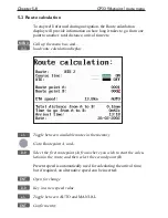
Page 68: ...u bar and 3 3 load route calculation display Toggle between available routes in the memory Go to Routepoint A and 0 9 Select the first routepoint A from where you wish to start the calcu lation in the route and then select the second point B Present speed is automatically used for calculating the arrival time but if required an alternative speed can be inserted ENT Open for change 0 9 Key in a new...

Page 69: ... on the chart To draw new lines you need a chart in the active window place the cursor where you wish to start the line and press PLOT Then follow the instructions in the info windows Refer to section 3 3 9 Lines can also be edited directly on the chart via info windows refer to section 3 3 4 and 3 3 5 MENU Call up the menu bar and 3 4 load line list display only plotted lines saved in the memory ...

Page 70: ...ype or color Toggle between available values ENT Confirm entry 5 4 1 Delete lines via menu MENU Call up the menu bar and 3 4 load line list Select the line you wish to delete ENT Open for editing GOTO Delete line CLR Confirm that you want to delete the selected line if not sure press MENU to exit the display without having made any changes Edit lines directly on the chart via info windows refer to...

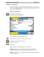
Page 71: ...e menu bar and 3 5 load Start track pop up window If you wish to change the default values Move cursor to where you wish to make a change Toggle between available values or 0 9 key in new values ENT Start track Name of track can be altered max 25 characters Display track can be set ON and OFF where OFF will make it invisible on the screen Turn ON to put it back on the screen Update of the track ca...

Page 72: ...dow ENT Stop the highlighted track 5 6 Tracks stored in the memory All tracks of more than 1 trackpoint will automatically be stored in the memory To see which tracks are registered you can scroll through the list by MENU Call up the menu bar and 3 7 load Tracks in active window A Z Select name of track or if a number is included in the track name place cursor on the number and Toggle up down in t...

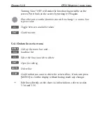
Page 73: ...ilable values ENT Confirm changes 5 6 1 Delete tracks via menu MENU Call up the menu bar and 3 7 load track display Select the track you wish to delete ENT Open for editing GOTO Delete track CLR Confirm that you want to delete the selected track if not sure press MENU to exit the display without having made any changes Edit tracks directly on the chart via info windows refer to section 3 3 6 ...

Page 74: ...otted target position is automatically preset to actual position of ship or to cursor position when the chart display is active and the cursor is on see INFO windows section 3 3 7 MENU Call up the menu bar and 3 8 load target display Make the target invis ible on the screen by turning it OFF Put it back on the screen by turning it ON again Select the target you wish to change or replace with a dif...

Page 75: ... up the menu bar and 3 8 load target display Select the target you wish to delete ENT Open for editing GOTO Delete target CLR Confirm that you want to delete the selected target if not sure press MENU to exit the display without having made any changes Edit targets directly on the chart via info windows refer to section 3 3 7 ...

Page 76: ...Chapter 5 16 CP33 Waypoint route menu ...

Page 77: ...n mode active See also section 6 2 Pilot menu with NAV active section 6 3 Anchor guard section 6 4 MOB navigation and 6 5 Navigation examples PILOT 6 1 Highway display MENU Call up the menu bar and 4 1 load Highway display Since there is no navigation mode active you will receive the legend NAVIGATION IS OFF To enter the basic Navigation setup display ENT Load Navigation setup see display example ...

Page 78: ...nywhere between 0 01 and 9 99nm See also section 6 3 Anchor guard The alarm will automatically reset once you are inside the limits again WP circle alarm forms a circle around each waypoint and the alarm distance can be set to anywhere between 0 01 and 9 99nm The waypoint alarm will be activated when you reach the circle or the perpendicular line WP line alarm crossing through the waypoint When Au...

Page 79: ...ine border When Auto waypoint shift is set to WP circle then the alarm function at the waypoint s circle will not be activated 6 2 Pilot menu with NAV active 4 PILOT 1 Highway see section 6 2 1 2 Turn NAV off see section 6 2 3 3 WP advance see section 6 2 4 4 Restart to approaching point see section 6 2 5 5 ETA AVN see section 6 2 6 6 Trim highway see section 6 2 7 7 Set drift see section 6 2 8 Th...

Page 80: ...en two waypoints XTE alarm lines refer to sec 6 1 for alarm setup Ship s posi tion and heading in relation to intended track C Course over ground X XTE Cross track error S Speed over ground B Bearing to approaching point D Distance to approaching point V Speed towards point Route Name number of active route and aproaching routepoint BN Bearing to next point TDG Total distance to go to end of route...

Page 81: ... menu bar and 4 2 turn off navigation mode 6 2 4 Pilot mode Waypoint advance MENU Call up the menu bar and 4 3 activate shift to next waypoint it will require that navigation mode is active and that a next way point exists 6 2 5 Pilot mode Restart to approaching point MENU Call up the menu bar and 4 4 activate restart to approaching point if you for some reason have drifted off course and wish to ...

Page 82: ...tion the approaching point and present speed over ground AUTO is automatically used for the calculation You can change to any waypoint in the route and also insert an alter native ETA speed MANUAL ENT Open for change in route navigation the approaching point is auto matically suggested and present speed is used for calculation If required go to and 0 9 Insert alternative routepoint only in Route n...

Page 83: ...og and compass The Trim highway display will provide information on actual and mean speed velocity and water speed see also section 6 2 8 Set drift display MENU Call up the menu bar and 4 6 load the Trim highway display B Bearing X XTE Cross track error D Distance to point ENT Open for change ENT Reset mean speed indication in display ...

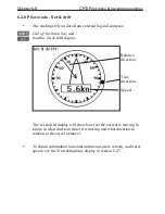
Page 84: ...r and 4 7 load the Set drift display Relative direction True direction Speed The set drift display will show how fast the current is moving in knots in what direction true it is moving and what direction in relation to the vessel relative To obtain information on actual and mean speed velocity and water speed see the Trim highway display in section 6 2 7 ...

Page 85: ...ys ENT Confirm the change To turn Anchor guard off again MENU Call up the menu bar and 4 2 turn anchor guard off 6 4 MOB alarm and navigation The MOB Man overboard alarm and display will be activated if you press the MOB key on the CP33 keypad and hold it depressed for two seconds or activate an external MOB switch hold two sec onds The MOB display will provide all relevant data for an effi cient ...

Page 86: ...tual and mean speed over ground velocity VMG and water speed section 6 2 7 the Set drift display with indication of how fast the current is moving in knots in what direction true it is moving and what direction in relation to the vessel relative see section 6 2 8 These readings rely on data from external log and compass With the PILOT key you can toggle between PILOT 6 5 1 Chart cursor navigation ...

Page 87: ... position to destination To turn NAV mode off again GOTO Press GOTO and 3 to 3 Turn NAV off from active chart display or MENU Press MENU and 4 2 to 4 2 Turn NAV off via the menu 6 5 2 Waypoint navigation There are two ways of activating Waypoint navigation From the chart display using GOTO or from the menu system From the chart CHART Shortcut to chart display Place cursor on destination waypoint G...

Page 88: ...il to Use the cursor to scroll up down in the waypoint list or place cursor on the WP number and Scroll up down with keys or 0 9 Key in the number of the waypoint you wish to sail to ENT Start navigation A course line will now be drawn from ship s position to destination waypoint To turn NAV mode off again GOTO Press GOTO and 3 to 3 Turn NAV off from active chart display or MENU Press MENU and 4 2...

Page 89: ...tcut to chart display Place cursor on the routepoint you wish to start your navigation from GOTO Select NAV mode and 3 Select Route This will activate the pop up window Navigate in route with the selected routepoint as first destination now follow the procedures from the a few lines further ahead or press ENT to start naviga tion From the menu MENU Call up the menu bar and 4 3 select Route navigat...

Page 90: ... the following functions to choose from 1 Advance to next routepoint 2 Restart to approaching point in case you have drifted off course 3 Turn NAV OFF MENU Pressing MENU and 4 from an active data display during naviga 4 tion will give access to the following displays features 1 Highway 2 Turn NAV off 3 WP advance to next routepoint 4 Restart to approaching point in case you have drifted off course...

Page 91: ... Velocity Necessary see section 6 2 6 Call up the Set drift display see section 6 2 8 There are two ways of activating Track navigation From the chart display using GOTO or from the menu system From the chart CHART Shortcut to chart display Place cursor on the track at the point where you wish to start your navigation from GOTO Select NAV mode and 4 Select Track This will activate the pop up windo...

Page 92: ...on GOTO Pressing GOTO from chart display during navigation will activate an INFO window with the following functions to choose from 1 Advance to next trackpoint 2 Restart to approaching point in case you have drifted off course 3 Turn NAV OFF MENU Pressing MENU and 4 from an active data display during naviga 4 tion will give access to the following displays features 1 Highway 2 Turn NAV off 3 WP a...

Page 93: ...ent in relation to time or distance ECHO Hotkey to Depth temperature diagram i e jumps to page with actual display if none inserts the last active Depth temperature diagram in active page or select via menu MENU Call up the menu bar and 5 6 activate Depth temperature diagram Present water temperature and depth Depth over time or dis tance Temperature over time or distance ENT Call Setup for Depth ...

Page 94: ...om 0 10m to 0 3000m Toggle between values with keys Color for depth and temperature can be changed Toggle between available colors by means of the keys Scale for temperature can be set to 0 10 0 20 0 30 10 20 and 10 10 Interval of screen the interval for updating of screen can be related to TIME or DISTANCE TIME interval can be set in 6 intervals from 5 minutes to 3 hours freeze for refreshing of ...

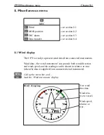
Page 95: ...lay The CP33 is ready to present wind data from connected instruments Wind data the wind instrument can provide both wind direction and wind speed and the readings can be shown in relative or true when the data is supplied from connected wind instrument MENU Call up the menu bar and 6 1 load the Wind instrument display True wind direction Wind rela tive to vessel Wind speed relative or true ...

Page 96: ...sh to change Toggle between settings or 0 9 Key in new figure ENT Confirm entry and return to Wind display Damping level can be set to LOW MEDIUM or HIGH The higher level the more steady and slow reacting reading Relative wind scale can either be set to NORMAL 0 180 or MAGNIFIED 0 60 Wind angle offset can be from 0 to 360 Show wind speed as TRUE or RELATIVE Wind speed unit can be either METER SECO...

Page 97: ...B position To delete a MOB track from the memory see section 3 3 6 8 3 DSC alarm feature prepared for future DSC VHF To receive a DSC Alarm and Message from VHF will require that the CP33 is connected to a compatible Simrad VHF radiotelephone The message from the VHF will appear in a pop up window together with an acoustic alarm Press CLR to reset the alarm To view the last received message MENU C...

Page 98: ...he DataCard is divided into two databanks of each 450 Kb meaning that the entire internal memory can be stored in one databank External memory with data transfer via DataCard MENU Call up the menu bar and 6 4 load the Data transfer window Data transfer 1 DataCard 7 NMEA connection see section 8 5 MENU Exit 1 Select the DataCard function DataCard 1 DataCard status 3 Save on DataCard 9 Load from Dat...

Page 99: ... to data already transferred Whenever transferring data from a CP33 to Databank 1 or 2 on the DataCard or from Databank 1 or 2 on DataCard to a CP33 the data package will replace the entire capacity in the receiving unit Load from DataCard 9 Press 9 to call up a new INFO window where you can see which data is stored in Databank 1 or 2 on the DataCard Use the keys to toggle between DATABANK 1 and 2...

Page 100: ... to and from a route planning program on a Personal Computer can be made via NMEA connection see section 10 7 by means of the standard NMEA0183 sentences WPL and RTE The data transfer on these two sentences does not include WP sym bol color XTE limit etc Refer to section 10 6 for information on connection to PC MENU Call up the menu bar and 6 4 load the Data transfer window Data transfer 1 DataCar...

Page 101: ... a new info window informing of how many waypoints were transferred MENU Exit function and return to normal NMEA communication Transmit routes 3 Press 3 to start transmission of all routes stored in the CP33 Route list to PC When the transmission is completed you will receive a new info window informing of how many waypoints and routes were trans ferred MENU Exit function and return to normal NMEA...

Page 102: ...oute list However if two waypoint route names are identical the latest transferred one will not be saved even though position s may be different Routepoints will not be included in the WP list Saving the collected data can take anywhere from less than a second and up to a few minutes depending on the amount of data If it takes too long and you need the CP33 in a hurry then press the MENU key to St...

Page 103: ...7 1 load Speed alarm units language display Setup for speed LOG speed sensor ON LOG speed calibration 019000 PULSES nm Speed alarm maximum SOG 000 0kn OFF Speed alarm minimum SOG 000 0kn OFF To select new values for this setup display see next page Setup for units Depth altitude in METERS Distance in NAUTICAL MILES Speed in KNOTS Temperature in DEGREE CELCIUS Software version CP33 1 11 PAGE More 1...

Page 104: ...or via ECHO port set to OFF and NMEA sentence VHW set to ON the readout will show water speed from external water speed instrument via NMEA port LOG speed calibration calibrate log speed readout by increasing decreasing the number of pulses per nautical mile see also Appen dix A Speed alarm can be set to maximum and or minimum cruising speed This may be handy for trawl fishing entering harbors wit...

Page 105: ...indicates the unit s serial number Interface software version indicates which version is installed in the unit for technicians only GPS receiver type indicates which type is installed in the unit for technicians only PAGE rotation interval can be set to anywhere between 03 to 99 seconds Refer to Fundamentals of the display and page system in section 2 1 for more details on how the function works D...

Page 106: ...ace setups will follow a description of the input and output sentences available in the setups MENU Call up the menu bar and 7 2 load NMEA interface PAGE Toggle between the three pages of sentences refer to 9 2 1 default settings and 9 2 2 description of sentences Toggle between INPUT and OUTPUT Go to and Toggle between individual settings i e NMEA0183 EXT DGPS NMEA0180 NMEA0182 Go to any sentence...

Page 107: ...ce setup INPUT Port NMEA0183 Sentence String Status Wind data Relative wind MWV ON True wind MWV ON Water data Water temperature MTW ON Water speed and heading VHW OFF Depth DPT DBT ON Heading data Heading HDG ON Position data External pos data OFF Datum 000 Name World Geodetic System 1984 Position GLL ON Course VTG ON Speed VTG ON Waypoint data Waypoint location WPL ON Target data Target Lat Lon ...

Page 108: ...of NMEA0183 version 2 0 output sentences Output must be set to NMEA0183 to receive input GGA is invalid when operating on external position GLL Geographic position latitude longitude GL2 Geographic position with 2 decimals GGA Global Positioning System fix data APB Autopilot sentence B BWR Bearing and distance to waypoint Rhumbline BWC Bearing and distance to waypoint Great circle RMB Recommended ...

Page 109: ...ffset MTW Water temperature Description of NMEA0183 external position heading and speed input Input is only valid when output is set to NMEA0183 GLL Geographic position latitude longitude RMA Recommended minimum specific Loran C data RMC Recommended minimum specific GPS data GGA Global Positioning System fix data VTG Track made good course and ground speed The external position can be set to OFF O...

Page 110: ...ay for Alarm output Interface setup alarm Output pin 1 2 ON Alarm stand by level LOW MENU Exit Accept ENT The stand by level can either be LOW 0 volt or HIGH 5 volt Use cursor to move around in display and Toggle between available settings ENT Confirm entry or MENU exit function without making any changes ...

Page 111: ...orth Humber 2A 27 Bombay 7B 04 Holland 2E 28 Calcutta 8B 05 British 3B 29 Bangladesh 6C 06 Lofoten Norway 3E 30 Hokkaido 9C 07 German 3F 31 Tohoku 6C 08 N Baltic 4B 32 Kyusyu 7C 09 NW Spanish 4C 33 Namaqua 4A 10 Trondelag N 4E 34 Cape chain 6A 11 English 5B 35 E Province 8A 12 N Bothnian 5F 36 Dampier 8E 13 S Spanish 6A 37 Port Hedld 4A 14 N Scottish 6C 38 Hokuriku 2C 15 Finland 6E 39 Newfoundld 2...

Page 112: ...available slaves not all chains have more than one slave 0 9 and it is possible to alter the figures in the time delay If required go to Offset and key in a positive or negative offset 0 9 Key in a positive or negative offset to the time delay toggle positive negative with ENT Confirm entry To change the position readouts to Loran C mode see section 4 1 under Position setup where Display position ...

Page 113: ...y color MENU Call up the menu bar and 7 6 load the Palette setup Palette 1 to 4 are preset to bright daylight sunshine in 1 and 2 normal daylight in 3 and night setting in 4 These four setups are not adjustable Palette 5 to 9 can be customized to suit individual needs and wishes If you wish to make your own special palette setup in e g palette 5 then 5 Select Palette setup 5 Use cursor to scroll u...

Page 114: ...Chapter 9 12 CP33 Setup menu Page 1 of 2 Page 2 of 2 ...

Page 115: ... presets but first check Troubleshooting in section 10 10 Activating Return to all factory presets will erase all user made settings including waypoints routes tracks etc and restore the basic settings from the factory Show test display Information in this display is for technicians only MENU Call up the menu bar and 7 7 activate the display for Factory settings DELETE MEMORY 1 Delete all WAYPOINT...

Page 116: ...nse from the keypad then first try to reset the unit by discon necting the power supply Reconnect the power cable and then start up the unit again by presssing and holding the PWR key until a picture appears on the screen MASTER RESET will return all settings to factory presets If the Power off reset does not solve the problem you may have to perform a master reset by disconnecting the power suppl...

Page 117: ...service 10 1 Installation notes For a number of reasons all user related decisions setups etc should be noted in these two pages as they occur This information may be helpful if your unit has been updated with new software reset or in for service Important settings ...

Page 118: ...Chapter 10 2 CP33 Installation and service Important settings continued ...

Page 119: ...100 5 mm 4 CP33 Installation and service Chapter 10 3 10 2 Installation of CP33 Chartplotter The CP33 can be flat or bracket mounted overhead bulkhead or console Bulkhead mounting approx 10 tilt allowing space for connectors and cables Console mounting max tilt 45 ...

Page 120: ...table and convenient for navigation and general operation after considering the following conditions you can see the ship s bow when you raise or lower your eyes from the dis play there is limited exposure to direct sunlight to avoid overheating see envi ronment temperature limits in 10 11 Specifications there is good ventilation and minimum vibration the minimum distance to a magnetic compass is ...

Page 121: ... can be applied when perform ing the installation Refer to section 10 6 for details on pin bumbers CP33 DS33 10 4 1 Operation of DS33 Dual Station The main unit and the dual station operate in parallel All key commands are relayed to the main unit CP33 and the display pic ture is instantly transferred back via a high speed data bus HSDb Adjust light contrast in screen and background light in keypa...

Page 122: ...w the horizon Avoid installing the GPS antenna inside the beam areas Mounting of DGPS antenna MGL 3 Mount the antenna on a standard US 1 14 thread pipe or optional standard antenna mount Tighten firmly but only by hand no use of tools Attach the antenna cable to the TNC socket Mounting of GPS antenna RS5640 Loosen the screw 1 of the antenna adapter Guide the antenna cable 2 through the adapter and...

Page 123: ... white dot Dual station 1 to 1 5 Orange yellow dot Dual station 2 to 2 6 Blue white dot PC Link TxD 7 Blue yellow dot PC Link RxD Ship s Ground GPS Antenna 1 2 Red Supply 10 32 Volts 3 4 Black Supply NMEA In NC Rx Shield 9 Yellow Data in Rx 6 Green Return NMEA Out 5 Braid Tx Shield 7 White Data out Tx 8 Brown Return NMEA 2000 Optional Fuse 4 0A slow CP33 Installation and service Chapter 10 7 10 6 ...

Page 124: ...the rear of the cabinet and turn the plug s coupling ring clockwise until it makes a click 10 6 2 Fuse Warning A fuse should always be installed to protect the unit Using a fuse which is not specified for your equipment can cause it to blow the instant the CP33 is switched on or it will not protect the equipment as intended see fuse rating in section 10 11 Specifications 10 6 3 NMEA0183 interface ...

Page 125: ...le Sub D connector Orange white dot Pink Orange yellow dot CP33 Installation and service Chapter 10 9 10 7 Optional connections External alarm and function switch The REMOTE connector refer to section 10 6 includes connections for the dual station as well as the external alarm and function switch If connection to external alarm or function switch is required the remote cable must be cut and rejoin...

Page 126: ...ion of a mild dish detergent and water Wring out firmly before wiping the unit Never use cleaning solutions containing spirit or alcohol Electrical connections periodically check the electrical connections Make sure that connections are tight and that no cables are frayed or worn 10 9 Repair and service The CP33 is sealed and does not contain any user serviceable parts Opening of this unit will vo...

Page 127: ...n Disconnect power and connect power again Check via MENU 1 3 if C MAP chart is defective Remove C MAP chart if defective Return to factory presets see section 9 7 No GPS position update Check external position to be OFF refer to interface display in MENU 7 2 Check antenna and cable Replace antenna or cable Screen update is extremely slow Check that the stored Tracks and Routes not currently in us...

Page 128: ...nd automatic sequencing Interfacing 1 port in out NMEA 0183 0182 0180 PC up download WPL and RTE 1 port NMEA 2000 optional Alarm signal output 5 V 50 mA Fuse 4 0A slow GPS section Receiver type 14 channel parallel C A code 8 state Kalman filter Accuracy Position DGPS 2 5 m RMS Position SDGPS 3 7 m RMS Position GPS 8 m RMS Speed 0 1 kn Course 1 Speed filter 10 settings Update rate 1 second interval...

Page 129: ...h combinations of or totals up to 35 000 marks waypoints 10 000 waypoints with name 25 characters 50 000 trackpoints 50 000 line sections 1 000 routes Options Simrad DataCards C MAP NT electronic charts 6 channel NMEA Buffer RS5345 PC data cable 1 5 m 153 6070 006 Antenna cable 15 m RG58 DS33 Dual Station 5 7 TFT LCD color screen or 6 monochrome incl 12 5 m cable 153 6070 004 max length 25 m Sunho...

Page 130: ...Chapter 10 14 CP33 Installation and service ...

Page 131: ... your needs You may set Units of measure feet fathoms meters etc Menu languages Scroll speed etc dGPS differential data is received from built in DGPS module or an exter nal DGPS Receiver ETA Estimated Time of Arrival at a specific waypoint if keeping a steady speed Great circle the shortest distance between two points on the globe Grid on chart can be set to AUTO ON OFF ON the grid is always visi...

Page 132: ...on in off season Navigation to cursor or waypoint in route or in track is started as described in chapter 6 The navigation simulator is started via the NMEA interface setup Press MENU 7 2 PAGE go to OFF next to External pos data and press the key to toggle to Dead reck move cursor to the right and enter a speed value of e g 10 knots press ENT twice The ship symbol will now sail to the point of des...

Page 133: ...ots kilometers and miles Starboard side right green TFT Thin Film Transistor Active matrix display UTC Universal Time Coordinates which is equal to standard time in London GMT UTC is not affected by the local summertime adjustments Velocity speed towards approaching waypoint Waypoint name a name can be added to each waypoint for easy identifica tion WPplot instant storage of actual position as a w...

Page 134: ...Appendix A 4 CP33 Glossary of terms ...

Page 135: ...y 025 Campo Inchauspe 026 Canton Astro 1966 027 Cape 028 Cape Canaveral 029 Carthage 030 Chatham 1971 031 Chua Astro 032 Corrego Allegre 033 Djakarta 034 DOS 1968 035 Easter Island 1967 036 Gandajika Base 037 Guam 1963 038 GUX 1 Astro 039 Hjorsey 1955 040 Hong Kong 1963 041 Indian 042 Ireland 1965 043 ISTS 073 Astro 1969 044 Johnston Island 1961 045 Kandawala 046 Kerguelen Island 047 Kertau 1948 0...

Page 136: ...84 095 World Geodetic System 1972 096 World Geodetic System 1984 097 World Geodetic System 1984 098 World Geodetic System 1984 099 Lisboa Datum 100 Pulkovo 1942 101 North Am 1927 Alaska Can 102 South American Yacare 103 Old Hawaiian Maui 104 Old Hawaiian Oahu 105 Old Hawaiian Kauai 106 Bukit Rimpah 107 Camp Area Astro 108 Guam 1963 109 G Segara 110 Herat North 111 HU TZU SHAN 112 Indian old 113 Qo...

Page 137: ... the cursor on a C MAP object and press ENT to call up an info window Scale 1 20000 Actual chart scale No user data at cursor position 1 Edit user data Inactive function 2 Chart info See details below 3 Find nearest port services See details below 4 Bearing and dist from A to B See sec 3 3 Info windows 9 Chart setup See sec 3 4 0 Cursor to center See sec 3 3 Info windows PAGE More user data Inacti...

Page 138: ...ines Press MENU to exit the function Service information Press the cursor key to activate the chart cursor ENT Press ENT from the chart display to call up the Info window 3 Find nearest port services will call up a list of symbols with rel evant information on each symbol Use the cursor to go to the object in the left column you wish to have information on e g the Port Marina symbol and then use t...

Page 139: ...tion Public Telephone Provisions etc The facility information will stay on the screen for about 10 seconds Tide information Press the cursor key to activate the chart cursor ENT Press ENT from the chart display to call up the Info window 3 Press 3 to call up the C MAP symbols with available facilities ...

Page 140: ...T to expand the information Example of Tide height information If you wish to see the low and high tides for a different date in the past or in the future it is possible to change the date Day In the display there will be a red box cursor on the number of the day in the month Toggle to a different number date with the keys Month Use the cursor to go to the present month Toggle to a different month...

Page 141: ...unctions is to select objects which are to be dis played on the screen chart The objects are organized in categories and each category can be selected as one without having to decide upon almost 300 objects separately Refer to section 3 4 Chart setup The following functions are used to enable disable visualization of the catego ries listed below LAND SETTINGS Natural features Land area and coastli...

Page 142: ...or facility Landing place Lock basin Oil barrier Ramp area Shoreline construction Slipway Weir line Small craft facility Coastguard station Pilot boarding place Rescue station Signal station warning Port area Harbor master Coast guard Police Customs Health emergency Post office Yacht club Boat yard Marine electronics Electric electronic repairs Engine repairs Sailmaker Fishing diving gear Scuba re...

Page 143: ...ritorial sea area Tracks routes Deep water route part Deep water route centrel Fairway Ferry route Navigation line Precautionary area Radar line Radar range Radio calling Recomm route centreline Recommended track Recomm traffic lane part Traffic separation line Traffic sep boundary Traffic sep crossing Traffic sep land part Traffic sep roundabout Traffic separation zone Two way route part Buoys Ca...

Page 144: ...Appendix C 8 CP33 C MAP attributes ...

Page 145: ...ntinued insert remove cartridge 3 5 objects organized in categories C 5 tide information C 3 Configuration A 1 Contrast light 2 7 Course over ground 4 5 4 6 A 1 filter 4 3 magnetic or true 4 1 Cursor function 3 3 chart cursor navigation 6 10 cursor navigation setup 6 2 Data transfer via DataCard 8 4 via PC interface 8 6 Datums 4 1 4 3 delta position 4 3 list of datums B 1 Daylight display 9 11 Dea...

Page 146: ...p 2 7 Installation antenna DGPS MGL 3 10 6 antenna GPS RS5640 10 6 CP33 10 3 DS33 10 5 location for display unit 10 4 notes 10 1 Interface setup alarm output 9 8 Interface setup NMEA 9 4 A 2 default sentences 9 5 description of sentences 9 6 return to NMEA presets 9 13 Interface software version 9 2 Introduction 1 1 Key functions 2 3 dedicated function keys 1 3 Key symbols in manual 1 2 Language 2...

Page 147: ...highway display 6 7 turn NAV off 6 5 waypoint advance 6 5 PLOT function 3 15 draw line 3 15 make route 3 15 plot ship s position as WP 3 15 plot target 3 15 plot waypoint 3 15 set vertical mark 3 15 Position display 4 1 menu 4 1 setup 4 3 start 4 3 Power off 2 8 Power on 2 7 Repair and service 10 10 Routes calculation 5 8 delete all 9 13 edit via chart 3 10 3 11 edit via menu 5 4 5 5 5 6 make new ...

Page 148: ... 6 15 navigation setup 6 2 start stop track 5 11 stored in the memory 5 12 trackpoints 5 11 Troubleshooting 10 11 UTC time and date 4 1 4 3 Warranty end of manual Waypoints auto waypoint shift A 1 delete all 9 13 edit via chart 3 9 edit via menu 5 2 menu 5 1 navigation 6 11 navigation setup 6 2 plot new waypoints 3 15 stored in the memory 5 1 WP list 5 1 Wind display 8 1 setup 8 2 wind direction 8...

Page 149: ...CP33 Chartplotter Index ...

Page 150: ...world wide use aboard non SOLAS vessels comply with the relevant essential requirements of Directive 1999 5 EC SIMRAD CE33 CP33 Chartplotters with GPS receiver Conformity assessment under Annex II of 1999 5 EC internal production control has been undertaken by Simrad Støvring AS Østre Allé 6 DK 9530 Støvring Denmark Telephone 45 98373499 Telefax 45 98373807 Signed 01 March 2002 Odin Sletten Produc...

Page 151: ...SERVICE OMBORD kan på forlangende arrangeres af den lokale autoriserede service forhandler eller national distributør Arbejdsløn for reparation udskiftning af defekte moduler dele er uden beregning ved bekræftelse af gyldig garanti Omkostninger ved overarbejde rejse og logi per dag forsikring told eller andre omkostninger er kundens ansvar Yderligere omkostninger i forbindelse med udskiftning af t...

Page 152: ..._______ UDSTYR ______________________________________________________________________ ____________________________________ ____________________________________ ______________________ __________________________ JA ________ NEJ ________ KØBSDATO INSTALLATIONSDATO INSTRUKTION I BRUG AF UDSTYR ___________________________________________ AUTORISERET INSTALLATØR FORHANDLERS STEMPEL Simrad Støvring AS Øs...

Page 153: ...________________ ___________________________________________ TYPE __________________________________________________________ UDSTYR ______________________________________________________________________ ____________________________________ ____________________________________ ________________________________________ ________________________________________ KØBSDATO INSTALLATIONSDATO ______________...

Page 154: ..._____________________________________ _________________________________________________________________________ _________________________________________________________________________ _________________________________________________________________________ PORTO ...

Reviews: