background image

7

SimpliFire •  SF-ALL40-BK, SF-ALL48-BK, SF-ALL60-BK, SF-ALL84-BK Service Manual  •  2040-960  Rev. G  •  5/20

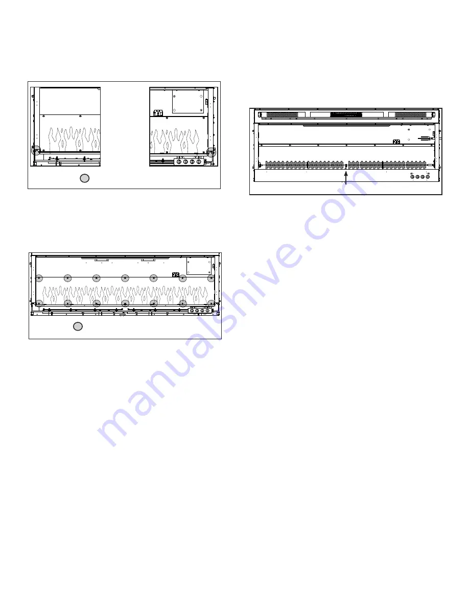
10.  Remove two (2) Phillips screws at the bottom of the 

       left and right side of the appliance opening.  See 

       Figure 15.

2 SCREW LOCATION

Screws at 

the bottom 

of the left  

and right side 

of appliance 

opening

SCREW LOCATION

11.   Remove Phillips screws at the top and bottom of  

        the flame screen.  See Figure 16.

12.

   Remove the flame screen.  


Note:

  Be sure to place on a flat surface with the


                    silk screen face-up. This is to prevent any  

                    distortion on the screen. 

13.  Remove the center screw located in the the center  

       of the Rotisseire.  Number of center supports may 

       vary.  See Figure 17.

CENTER SCREW LOCATION

14.   Pull the Rotisseire to the left to disengage it from  

        the motor, then remove the Rotisseire assembly.

Figure 15. Screw Location   

Figure 16.  Flame Screen Location   

Figure 17.  Rotisseire Screw Location

If replacing only the Rotisseire, 

install replacement 

part and reverse the installation steps.  

Be sure the flame screen is installed correctly with the 

flame silk screen to the outside and flames at the bottom 

of the appliance.

If replacing Motor 

continue to the next steps 15-18.

Rotisseire Installation

If replacing Flame LED Light Board continue to step 

19.

CAUTION!  Risks of Cuts!   

Rotisseire has sharp edges 

that can cut skin.  Always wear gloves when servicing the 

Rotisseire and/or Flame LED and/or Rotisseire Motor.

Summary of Contents for SF-ALL40-BK

Page 1: ... following tools and building supplies are available Tape measure Needle nose pliers Hammer Gloves Level Magnetic Phillips screwdriver Safety glasses Drill Flathead screwdriver Phillips Tip Bit socket and ratchet for Blower Heater 5 16 Drill for 3 16 diameter toggle bolts applicable if installing on drywall sheathed walls Masonry Drill 5 16 in applicable if installing on masonry walls Glass Front ...

Page 2: ... Installing Glass 3 Install front panel Locate the J hooks on the back side of the glass on the four rivnuts on the appliance opening Engage the rivnuts See Figure 2 4 Press down on top edge of glass to fully engage J hooks on the rivnuts Note Make sure the glass is fully attached to the fire box so that the control panel can work properly Figure 2 Glass Front Removal Installation 5 Thread the two...

Page 3: ...d from the receptacle 2 Remove the glass front from the appliance Use two people 3 Remove appliance the two screws in upper right and left corners of the glass opening Follow specific instructions from page 1 and 2 for removal of the front glass See Figure 4 CAUTION Two adults recommended for the removal or installation of glass front Use caution when han dling glass Failure to do so could result ...

Page 4: ...seven tabs as shown in Figure 6 Pry the tabs upward at a 30 degree angle During this step take care not to scratch or damage the glass panel behind the tabs FUELBED PLASTIC COVER TABS Figure 6 Remove Plastic Cover 6 Remove the fuelbed plastic cover that covers the fuelbed LED light strips See Figure 6 4 Remove right and left side panels by turning the panels inward See Figure 5 ...

Page 5: ...Board cable See Figure 9 LED LIGHT BOARD CABLE LED LIGHT BOARD CABLE Figure 8 LED Light Board Cable Figure 9 Unplug LED Light Board Cable 4 Remove the LED light board from the bottom isolation columns Starting at one end of the board use a needle nose pliers to compress the plastic barbs from each isolation column as each plastic barb is compressed disengage the LED light board from each barb See ...

Page 6: ...s the opening then lift out the the glass panel from the appliance Set glass panel aside in a safe location preferably a soft surface such as carpet or cardboard Figure 11 Fuelbed LED Light Board Screw Location Receiver Board Installation 6 Locate the Receiver Board in the upper right side of appliance See Figure 13 Figure 13 Reciever Board Location ISOLATION COLUMN ISOLATION COLUMN CABLE Figure 1...

Page 7: ...the Rotisseire Number of center supports may vary See Figure 17 CENTER SCREW LOCATION 14 Pull the Rotisseire to the left to disengage it from the motor then remove the Rotisseire assembly Figure 15 Screw Location Figure 16 Flame Screen Location Figure 17 Rotisseire Screw Location If replacing only the Rotisseire install replacement part and reverse the installation steps Be sure the flame screen i...

Page 8: ...nplug Motor Cable 18 Install replacement part and reverse the installation steps Flame LED Light Board Installation NOTE The following steps 15 18 are only for re placement of the motor If replacing Flame LED Light Board continue onto step 19 19 Remove screws used to attach the flame screen bracket See Figure 21 SCREW LOCATION Figure 21 Remove Flame Screen Bracket Screws 20 Remove flame screen bra...

Page 9: ...wires will be reconnected correctly See Figure 24 Figure 24 Unplug Control Board 25 Install new Control Board and reverse the installation steps Blower Heater Installation 26 Locate the four 4 screws on the mounting plate for the blower heater module See Figure 25 27 Remove the four 4 Phillips screws Figure 25 Remove Mounting Plate Screws 28 Drop the Blower Heater module down on the shelf See Figu...

Page 10: ...This product cannot be installed on a wall sheathed with drywall less than 1 2 in thick unless all six 6 anchor points in the mounting bracket align with structural framing members WARNING Risk of Damage or Personal Injury Al lowable pull out and shear strength are 25 of ultimate values or less as required by building authorities Framed Wall Locate the mounting bracket on the wall in the desired l...

Page 11: ... is stored or secure to avoid tripping and snagging Figure 32 Optional Power Cord Assembly Installation L N RED BLUE Wire Diagram YELLOW GREEN Power Cord Installation The appliance power cord has a three pin NEMA 5 15P plug The power cord should not be used unless a grounded receptacle is available 1 Remove the terminal block cover plate located on the right end of the appliance 2 Disconnect the t...

Page 12: ...circuit breaker and allow it to cool for 15 minutes Then plug in the unit or turn power back on at circuit breaker and turn unit back on Defective main control board Replace control board PCB Defective heater assembly Replace heater assembly Heater shuts off automatically or won t stay on Room temperature temperature at the appliance thermistor is higher than the set point on the remote Increase t...

Page 13: ...self Defective control board PCB Replace control board PCB Similar infrared signal from another remote causing unit to turn on pre 2019 manufactured units only Some TV remotes may cause the fireplace to turn on for appliances manufactured before 2019 Replace control board PCB Excessive noise with heater on Interference with fan blade Inspect heater assembly and fan for obstructions or interference...

Reviews: