Adjustments
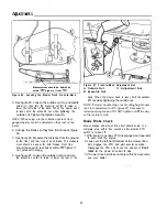
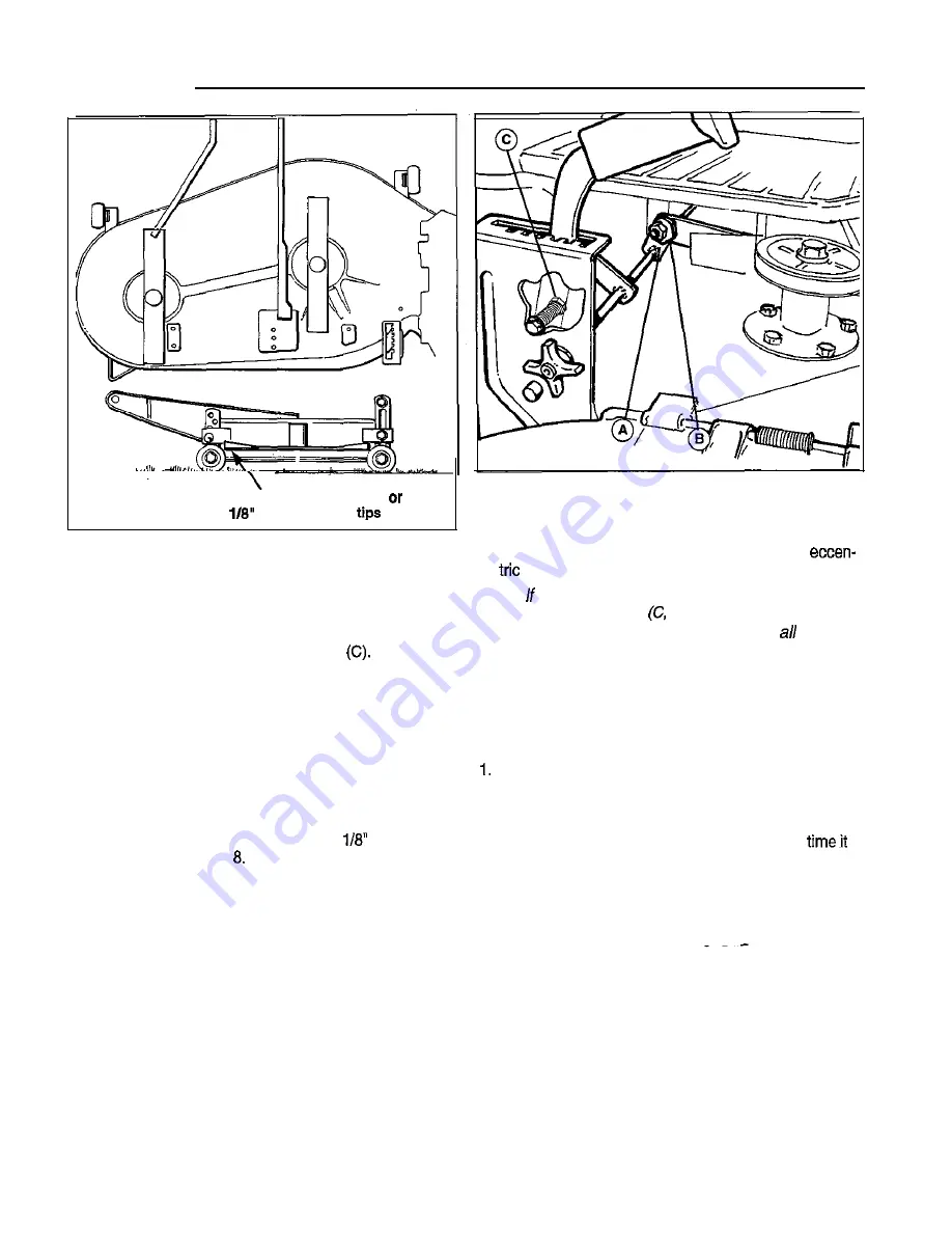
Measurement should be
equal
within
higher at front
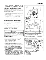
Figure 27. Front-to-Back Adjustment Nut
A. Outside Nut
C. Adjustment Nut
B. Eccentric Nut
Figure 26. Leveling the Mower Deck Front-to-Back
5. See figure 25. Loosen the outside nut (A) and taptite
screw (C), then turn the eccentric nut (B) to raise or
lower the left side of the deck. When the mower deck
is level, hold the eccentric nut while tightening the
outside nut. Tighten the taptite screw
NOTE: When using a turbo collection system, front
gauge wheels should be adjusted so they rest on the
ground.
deck. When the mower deck is level, hold the
nut while tightening the outside nut.
NOTE: mower handle drops out of cutting height quad-
rant, turn adjustment nut
figure 27) clockwise to
increase spring tension. DO NOT tighten nut
the way
so that spring is solid.
6. Arrange the blades so they face front-to-back (figure
26).
7. See figure 26. Measure the distance from the ground
to the front and rear tips of each blade. The measure-
ment should be equal for both blades. Front tips
should be equal to rear tips or within
higher. If
not, proceed to step
8. See figure 27. Loosen the outside nut (A) and turn
the eccentric nut (B) to raise or lower the rear of the
Blade Brake Check
Mower blades and mower drive belt should come to a
complete stop within five seconds after electric PTO
switch is turned off.
With tractor in neutral, PTO disengaged and operator
in seat, start the engine.
2. Look over the left-hand footrest at the mower drive
belt. Engage the PTO and wait several seconds.
Disengage the PTO and check the amount of
takes
for the mower drive belt to stop.
3. If mower drive belt does not stop within five seconds,
see your dealer.
24
Summary of Contents for 1692358
Page 32: ...INTERNATIONAL SYMBOLS 28 ...


