Simoco SRM9020PLUS Operating Instructions Manual Download Page 8

SRM9020

plus

 ~ PMR Operating Instructions


© Comgroup Australia 2010 

Page 24  

TNM-U-E-0086 Issue 1.0a


2. 

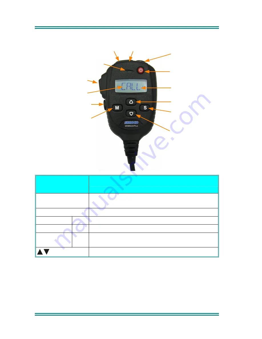
FRONT PANEL CONTROLS  

Volume Up

Volume Down

On/Off

Icons

Scroll Up

Scroll Down

F4 - Scan On/Off
or Send Selcall

F2 - Function

F3 - Return to Menu

F1 - Change Menu

Display

PTT

Microphone


BUTTON/ 
CONTROL 

FUNCTION 

On/Off 

Push and hold for 1 second to switch the radio 

On


or 

Off

PTT/Pressel 

Press-to-Talk switch. 

M

 (Menu)


F1 

Move between Menu Screens. 


F3 

Used to return to the Main Menu Screen. 

S


(Select) 

F4 

Used to make a call to the displayed identity, or 
activate 

Scanning


Scroll up and down through a list within a Menu. 

 
The four programmable buttons, F1 to F4, can be programmed, using the FPP 
Programmer, to perform different functions. If the default settings, described 
above, are changed, alternative means should be provided to perform their 
original functions.   
 

Summary of Contents for SRM9020PLUS

Page 1: ...SRM9020plus Mobile Radio Conventional PMR Operating Instructions TNM U E 0086 Issue 1 0a January 2010 abcde Comgroup Australia Pty Ltd 1270 Ferntree Gully Road Scoresby Victoria 3179 Australia...

Page 2: ......

Page 3: ...TNM U E 0015 SRM9025 Trunked Operating Instructions To order copies of any of the above publications or any other Simoco product contact Comgroup Australia on 61 3 9730 3800 or send a Fax on 61 3 9730...

Page 4: ...igns where these are posted e g on a petrol station forecourt 3 Do NOT touch the antenna while the radio is transmitting 4 Do NOT operate the radio if the antenna has become disconnected or damaged HI...

Page 5: ...and Icons 3 3 2 Switch On Switch Off 4 3 3 Volume Adjustment 5 3 4 Receiving 5 3 5 Transmitting 6 3 6 SELCALL Functions 7 3 6 1 Receiving a Selcall 7 3 6 2 Sending a Selcall 7 3 6 3 Other Selcall Fun...

Page 6: ...20 7 7 CTCSS 20 7 8 Mute 21 7 9 External Alert 21 7 10 Goto Chan A B C D 21 7 11 Alarm 21 7 12 Repeater Defeat 21 7 13 Low Power 21 7 14 Scrambler 21 8 OPTIONS 22 8 1 Quick Release Transceiver Kit 22...

Page 7: ...reach of the driver A speaker connected to the radio provides the audio interface The radio is software programmable and it can be customised to the operational requirements of your particular fleet Y...

Page 8: ...for 1 second to switch the radio On or Off PTT Pressel Press to Talk switch M Menu F1 Move between Menu Screens F3 Used to return to the Main Menu Screen S Select F4 Used to make a call to the display...

Page 9: ...e rotating icon indicates that the radio is searching for a channel e g while Voting The symbol disappears when stopped on a channel Scanning indicator shows that the radio is searching the channels i...

Page 10: ...brief time the display will show the selected channel at which time the radio is ready for use Pressing and holding the On Off button for approximately 2 seconds will switch the radio Off If the radio...

Page 11: ...d Channel Typical Icons are Indicates that a valid signal is present and can be heard from the loudspeaker Indicates that a signal with invalid CTCSS or Selcall is present and that the speaker is mute...

Page 12: ...e PTT button and commencing to speak This ensures that the path is properly established and avoids lost or distorted speech Use the correct operating procedure and keep transmissions short Release the...

Page 13: ...radle or pressing the PTT will stop any alerts and answer a received call 3 6 2 Sending a Selcall Refer to Phonebook Screen Section 5 2 and Status Screen Section 5 3 for methods of sending a Selcall 3...

Page 14: ...nel Screen to enter Scan Mode or select a channel that has been programmed as a scan channel 3 7 1 Scan Screen The display shows the name of the current Scan Group e g West which can be changed using...

Page 15: ...icrophone is left off cradle for too long then the radio will sound a continuous alert tone until it is replaced In the Scan Screen the function buttons are assigned as follows M Go to other menus F3...

Page 16: ...w the Radio Mute level to be adjusted The level is stored when the Screen is exited via the S button or times out 3 9 EXTERNAL ALERT Provision is made to connect an external alerting device to the rea...

Page 17: ...g page illustrates the default menu structure for which the radio is programmed at manufacture Any or all of the Screens can be programmed for access with the following proviso The Channel Screen is a...

Page 18: ...Navigation Buttons M Move through the available Main Screens S Select Setup Sub Menu Scroll Up down though Menu Lists F3 Return to Main Menu Default Channel This diagram shows a sample of available m...

Page 19: ...ored for various users and calls can be placed to them from this Screen From the Main Channel Menu press the M button until PhoneB is briefly displayed The display will quickly be replaced by the Curr...

Page 20: ...ain Channel Menu press the M button until Status is briefly displayed The display will quickly be replaced by the Saved Status Value The buttons scroll through the Status List entries Pressing the S b...

Page 21: ...button until Stored is displayed If there are entries in this menu the display will quickly change to show the most recently received calls The icon will show in the Main Channel Menu when there is a...

Page 22: ...EEN Use this Screen to access the other Setup submenus From the Main Channel Menu press the M button until Setup is displayed Press the S button to access the submenus When a submenu is displayed pres...

Page 23: ...operator functions as follows User Options Key beeps Display Illumination and Dual Watch on off selection Mute Adjust Mute Level adjustment Alert Volume Beep tone level setting relative to Audio Volum...

Page 24: ...y not be changed Press the M button to change to the Alert Volume submenu 6 1 3 Alert Volume This Screen allows you to set the level of the Alert Volume Beep Tone in relation to the current Volume set...

Page 25: ...y This is a read only Screen press the S button to go to the Channel Screen Press the M button to change to the Network submenu 6 1 5 Network The Network Screen allows you to switch operation between...

Page 26: ...rogrammed The display briefly shows ON or OFF when the button is pressed 7 2 SQUELCH DEFEAT Opens Closes the squelch carrier mute The display briefly shows ON or OFF when the button is pressed 7 3 RES...

Page 27: ...display briefly shows ON or OFF when the button is pressed 7 11 ALARM Puts the mobile into Alarm mode 7 12 REPEATER DEFEAT Allows the radio to transmit on the reverse frequency on a Repeater Channel W...

Page 28: ...t having to lift the microphone or press any buttons 8 4 TYPE 1 PARALLEL I O EXPANSION OPTION This option provides eight I O lines and pre de emphasised audio to allow external interfacing to the radi...

Page 29: ...is guide you are unable to switch the radio on check the following A fuse has not blown Your installer should advise you of the location of the two fuses The power supply cables and their connections...

Page 30: ...0086 Issue 1 0a APPENDIX A ALERT TONES AND MESSAGES Continuous Alert Urgent Alert Off All durations indicated in seconds 440Hz 880Hz 1480Hz Ring Alert 2 x Bip Alert Bip Alert Beep Alert Error Tone Key...

Page 31: ...thod Icon A symbol shown on the display LCD Liquid Crystal Display MPT1327 The UK Ministry for Post and Telecommunications specification defining the low level protocol for public trunking systems MPT...

Page 32: ...oup Australia 2010 TNM U E 0086 Issue 1 0a Hereby Comgroup Australia Pty Ltd declares that this product is in compliance with the essential requirements and other relevant provisions of Directive 1999...

Reviews: