background image

Installation

5

NOTICE:

Pump motor is equipped with carbon brushes

with a normal operating life of about 300 hours. One
extra set of brushes is included. Replacement brushes are
available from your dealer. Motor brushes not included
in warranty.

Fire hazard. Incorrectly mounted brushes

may cause fire.

Be sure curve on end of brush matches

curve on commutator.

LUBRICATION

Motor is lubricated at factory for life of bearings. Pump
seal is water cooled and self lubricating.

PUMP SERVICE

Motor has auto-reset thermal overload. If motor over-
heats, overload will cut off power to prevent damage
and will reset after motor cools. If overload trips repeat-
edly, check pump for cause (low voltage, clogged
impeller, etc.).

Hazardous voltage. Can shock, burn, or

cause death. Disconnect motor from electrical power
before servicing pump.
Always replace 

both brushes - to avoid fire hazard,

never replace just one.

Seal Changing Procedure

Hazardous voltage. Unplug pump before

continuing.

1. Unplug the pump from the outlet and remove all

piping or hoses from the pump.

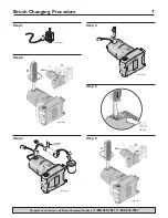
2. To avoid breaking the brushes when you remove or

replace the motor shaft, remove the motor brushes
(see “Brush Changing Procedure”, Page 7, Steps 1
and 2). Put the brushes where they will not get lost
or damaged while you proceed.

3. Remove 4 screws from the back of the pump body

(Key No. 1, Page 8) and remove the pump body
from the motor. Remove the old Square-cut O-Ring
(Key No. 4C) from the assembly.

4. Unscrew the impeller (Key No. 4A) from the motor

shaft and discard it.

5. Pull the seal plate (Key No. 5) from the motor shaft.
6. Turn the seal plate face down (See Figure 4A) and

use a screwdriver or small tube to push the station-
ary seal half out of the seal plate (Figure 4B).

7. Place a cardboard washer over the seal face to pro-

tect it and use a tube to push the stationary seal half
into the seal plate until it seats (Figure 4C). Be sure
you don’t scratch or mar the polished face of the
seal. Also, keep your hands away from the seal face
to keep dirt and grease off of it.

8. Use the cardboard washer and tube to push the

rotating half of the seal into the new impeller, pol-
ished face out (Figure 4D). Be sure you don’t scratch
or mar the polished face of the seal. Also, keep your
hands away from the seal face to keep dirt and
grease off of it.

9. CAREFULLY slide the seal plate back onto the motor

shaft, making sure that you don’t chip or scratch the
seal face in the process.

10. Thread the new impeller onto the motor shaft, 

making sure that you don’t chip or scratch the seal
face in the process.

11. Reinstall the motor shaft in the motor.
12. Install the new square-cut O-ring on the seal plate.
13. Bring the impeller/motor assembly up to the pump

body and insert the impeller and seal plate into the
pump body.

14. Install the 4 body screws (be sure to reinstall the

handle on the upper screws) and tighten them
securely.

15. Replace the motor brushes (see “Brush Changing

Procedure”, Page 7, Steps 4, 5, and 6).

For parts or assistance, call Simer Customer Service at 

1-800-468-7867 / 1-800-546-7867

A

B

C

5678 0807

Figure 4: Seal Changing Procedure

Summary of Contents for 4850C

Page 1: ...stalación o mantenimiento de la bomba Llame al 1 800 468 7867 Español Paginas 16 22 SIM819 Rev 5 12 08 IN OUT Model 4850C 293 Wright St Delavan WI 53115 Phone 1 800 468 7867 1 800 546 7867 Fax 1 800 390 5351 Risk of fatal electrical shock if pump motor gets wet Keep motor dry Do not immerse pump or motor or run pump if motor is wet Risque d électrocution si le moteur de la pompe entre en contact a...

Page 2: ...not pump gasoline or any other flammable liquids with pump Do not use pump in atmosphere that might contain flammable fumes or vapors 6 Do not pump chemicals or corrosive liquids with pump If water is trapped in pump during opera tion it may turn to steam leading to explosion and burns Never run pump with outlet shut off or blocked NOTICE Pump clean water only with pump To avoid clogging pump and ...

Page 3: ...ation maintenance or storage nor to other than normal application use or service including but not limited to operational failures caused by corrosion rust or other foreign materials in the system or operation at pressures in excess of recommended maximums Requests for service under this warranty shall be made by returning the defective product to the Retail outlet or to SIMER as soon as possi ble...

Page 4: ...ervicing it Do not handle pump or attempt to work on pump with wet hands or while standing on wet or damp floor Plug pump into 115 Volt 60 Cycle outlet only Pump is equipped with 3 wire grounded cord and plug Do not modify or remove plug Plug in to properly grounded grounding type outlet only Make sure pump circuit meets National Electrical Code To avoid dangerous elec trical shock hazard keep cor...

Page 5: ...y 4 Unscrew the impeller Key No 4A from the motor shaft and discard it 5 Pull the seal plate Key No 5 from the motor shaft 6 Turn the seal plate face down See Figure 4A and use a screwdriver or small tube to push the station ary seal half out of the seal plate Figure 4B 7 Place a cardboard washer over the seal face to pro tect it and use a tube to push the stationary seal half into the seal plate ...

Page 6: ...re copper shows If you see any bare wire disconnect the wire nut and remake that connection 7 Once you are sure that there is no exposed wire carefully stuff the wire and wire nuts back into the cavity in the motor 8 Hold the cord plate up against the motor and rein stall the screws Tighten thoroughly but do not over tighten 9 Once assembly is complete SET THE PUMP DOWN that is don t touch it and ...

Page 7: ...ts or assistance call Simer Customer Service at 1 800 468 7867 1 800 546 7867 5602 0407 5604 0407 A B T UT N OUT IN OUT 5605 0407 IN OUT 5606 0407 IN OUT 5607 0407 Step 1 Step 2 5604 0407 UT IN OUT IN OUT A B Step 6 Step 3 Step 4 Step 5 ...

Page 8: ... 4C 1 FPPKG 225 P2 4A Impeller 1 4B Shaft Seal 1 4C Square Cut O Ring 1 5 Seal Plate 1 6 Handle With Hardware 1 C54 30 7 Power Cord 1 PS17 1507 8 Brush Kit Includes 1 Pair of Brushes with springs and Retainer Caps 1 FPPKG 226 P2 9 Motor 1 If Pump Body or Motor fail replace entire pump NOTE Fill Plug threads do not match inlet or discharge threads Fill Plug is not interchangeable with Garden Hose A...

Page 9: ...sence ou tout autre liquide inflammable avec cette pompe ni l utiliser dans un environnement pou vant contenir des vapeurs ou gaz inflammables 6 Ne pas pomper de produits chimiques ou corrosifs avec cette pompe Si de l eau est retenue dans la pompe pendant le fonctionnement de la vapeur peut se créer causant une explosion et des brûlures Ne jamais faire fonctionner la pompe avec la decharge en cou...

Page 10: ...normalement y compris mais sans s y limiter aux produits ayant des pannes de fonctionnement causées par la corrosion la rouille ou autre corps étranger dans le système ou à des produits ayant fonctionné à des pressions dépassant la limite maximale recommandée Les demandes de service en vertu de la présente garantie seront faites en retournant le produit défectueux au détaillant ou à SIMER dès la d...

Page 11: ...UES Risque d électrocution dangereuse voire mortelle Débrancher la pompe avant de passer à l entretien Ne pas manipuler la pompe ou y travailler avec les mains mouillées en ayant les pieds en contact avec de l eau ou en se tenant sur un sol mouillé Ne brancher la pompe que sur une sortie de 115 volts 60 cycles Cette pompe est équipée d un câble et d une prise à 3 fils métalliques et à masse Ne pas...

Page 12: ... Dévisser l impulseur Réf 4A de l arbre du moteur puis le jeter 5 Sortir la plaque d étanchéité Réf 5 de l arbre du moteur 6 Tourner la plaque d étanchéité à l envers voir la Figure 4A puis à l aide d un tournevis ou d un petit tube pousser sur la moitié du joint fixe pour la sortir de la plaque d étanchéité Figure 4B 7 Poser une rondelle en carton sur le joint pour le pro téger puis à l aide d un...

Page 13: ...xposé déposer le serre fil et refaire la connexion 7 Dès qu on est sûr qu aucun fil nu n est exposé pousser prudemment les fils et les serre fils dans la cavité du moteur 8 Immobiliser la plaque du cordon électrique contre le moteur puis reposer les vis Bien les serrer mais pas exagérément 9 Lorsque le remontage est terminé POSER LA POMPE À TERRE c est à dire qu il ne faut pas la toucher puis bran...

Page 14: ...ces ou de l aide appeler le Service à la clientèle Simer en composant le 1 800 468 7867 1 800 546 7867 5602 0407 5604 0407 A B T UT N OUT IN OUT 5605 0407 IN OUT 5606 0407 IN OUT 5607 0407 Étape 1 Étape 2 5604 0407 UT IN OUT IN OUT A B Étape 6 Étape 3 Étape 4 Étape 5 ...

Page 15: ... 4B Joint d arbre 1 4C Joint torique à taille carrée 1 5 Plaque d étanchéité 1 6 Poignée et fixations 1 C54 30 7 Cordon électrique 1 PS17 1507 8 Trousse de balais comprend 1 paire de balais les ressorts et 1 FPPKG 226 P2 les bouchons 9 Moteur 1 Si le corps de la pompe ou si le moteur tombe en panne remplacer la pompe au complet REMARQUE Le filetage du bouchon de remplissage n est pas le même que c...

Page 16: ...flamable No use la bomba en una atmósfera que pueda contener humos o vapores inflamables 6 No bombee productos químicos o líquidos corrosivos Si queda atrapada agua en la bomba durante la operación puede convertirse en vapor produciendo una explosión y quemaduras No haga funcionar nunca la bomba con la salida cerrada o bloqueada AVISO Utilice la bomba con agua limpia solamente Para evitar que se o...

Page 17: ...ntenimiento o alma cenaje incorrectos ni a ninguna otra cosa que no sea su aplicación uso o servicio normales incluyendo pero no limitado a fallas operacionales causadas por corrosión oxidación u otros elementos extraños en el sistema o funcionamiento a presión por encima del máximo recomendado Los pedidos de servicio bajo los términos de esta garantía serán efectuados mediante la devolución del p...

Page 18: ... misma No toque la bomba ni intente trabajar en la misma con las manos mojadas o estando parado sobre un suelo mojado Enchufe la bomba solamente en una toma de corriente de 115 voltios y 60 ciclos La bomba está equipada con un cordón de 3 conductores conectado a tierra y un enchufe No modifique ni quite el enchufe Enchufe el cordón en una toma de corri ente conectada a tierra de forma adecuada Cer...

Page 19: ...ico de corte recto usado Referencia No 4C de la unidad 4 Destornille el impulsor Referencia No 4A del eje del motor y descártelo 5 Saque la placa de estanqueidad Referencia No 5 del eje del motor 6 Coloque la placa de estanqueidad boca abajo consulte la Figura 4A y use un destornillador o un tubo pequeño para empujar la mitad fija de la junta y sacar la de la placa de estanqueidad Figura 4B 7 Colo...

Page 20: ...xpuestos cuidadosamente introduzca los cables y los conec tores del cable nuevamente en la cavidad del motor 8 Sostenga la placa del cordón contra el motor y vuel va a instalar los tornillos Apriételos firmemente pero no demasiado 9 Cuando haya terminado de ensamblarla DEJE LA BOMBA EN POSICIÓN es decir no la toque y enchúfela muy brevemente para evitar dañar la junta del eje para verificar que to...

Page 21: ...sita repuestos o asistencia llame al Servicio al Cliente de Simer 1 800 468 7867 1 800 546 7867 5602 0407 5604 0407 A B T UT N OUT IN OUT 5605 0407 IN OUT 5606 0407 IN OUT 5607 0407 Paso 1 Paso 2 5604 0407 UT IN OUT IN OUT A B Paso 6 Paso 3 Paso 4 Paso 5 ...

Page 22: ...del eje 1 4C Aro tórico de corte recto 1 5 Placa de estanqueidad 1 6 Mango con accesorios de ferretería 1 C54 30 7 Cordón eléctrico 1 PS17 1507 8 Juego de escobillas Incluye 1 par de escobillas con resortes y casquetes de retención 1 FPPKG 226 P2 9 Motor 1 Si la Unidad de la bomba o el motor fallan reemplace toda la bomba NOTA Las roscas del tapón de llenado no concuerdan con las roscas de admisió...

Page 23: ...23 ...

Page 24: ......

Reviews: