5,000.cm
2
.for.gas.with.a.density.gre-
ater.than.0.8.
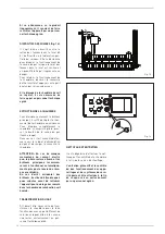
2.1.1 Handling
Once.the.boiler.is.in.its.place.of.instal-
lation. and. the. packaging. has. been.
removed,.proceed.as.follows.if.it.must.
be.moved.(fig..3/a):
–. remove.the.casing.cover;
–. attach. the. lifting. brackets. (located.
on.the.rear.of.the.boiler).and.fasten.
it.in.place.with.the.screws.provided;
–. insert.two.3/4”.pipes.in.the.holes.in.
the.brackets,.lift.the.boiler.carefully.
and.place.into.position.
2.2
CONNECTING
UP SYSTEM
Before. proceeding. to. connect. up. the.
boiler,.you.are.recommended.to.make.
the. water. circulating. in. the. piping. in.
order. to. eliminate. any. foreign. bodies.
that.might.be.detrimental.to.the.ope-
rating.efficiency.of.the.appliance..
The. unit. must. be. connected. up. with.
rigid.pipe.fittings.which.will.not.subject.
it.to.stress.of.any.kind..
The. connections. should. be. easy. to.
disconnect. using. pipe. unions. with.
orientable. connections.. You. are.
recommended.to.install.suitable.shu-
toff. valves. on. the. system. flow. and.
return.pipes..
In order to achieve a good water
distribution inside the cast-iron body,
the system flow and return pipes
should be connected to the same side
of the boiler.
.
The boiler comes supplied standard
with the attachments on the right-
hand side, with the possibility of them
being transferred to the left-hand
side.
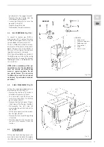
In that case, move the water distribu-
tor, located on the return header, and
the thermostat bulbs located in the
sheathe, to the same side.
The. thermal. jump. between. the.
system. flow. and. return. pipes. should.
not. exceed. 20°C.. For. this. purpose,. it.
is. advisable. to. install. a. mixer. valve.
with.corresponding.anti-condensation.
pump.
CAUTION: The system circulation
pump or pumps must go into action
at the time of boiler ignition.
For this purpose, you are recommen-
ded to use an automatic system of
precedence.
The. gas. connection. must. be.
made. using. seamless. steel. pipe.
(Mannesmann. type),. galvanized. and.
with. threaded. joints. provided. with.
gaskets,. excluding. three-piece. con-
nections,. except. for. initial. and. end.
connections..
Where. the. piping. has. to. pass. throu-
gh. walls,. a. suitable. insulating. sleeve.
must.be.provided..
When.sizing.gas.piping,.from.the.meter.
to. the. boiler,. take. into. account. both.
the. volume. flow. rates. (consumption).
in.m
3
/h.and.the.relative.density.of.the.
gas.in.question..
The.sections.of.the.piping.making.up.
the. system. must. be. such. as. to. gua-
rantee. a. supply. of. gas. sufficient. to.
cover.the.maximum.demand,.limiting.
pressure.loss.between.the.gas.meter.
and. any. apparatus. being. used. to. not.
greater.than:
–. 1.0.mbar.for.family.II.gases.(natural.
gas);
–. 2.0.mbar.for.family.III.gases.(butane.
or.propane).
An.adhesive.data.plate.is.sticked.insi-
de. the. front. panel;. it. contains. all. the.
technical. data. identifying. the. boiler.
and.the.type.of.gas.for.which.the.boiler.
is.arranged.
2.3
CHARACTERISTICS
OF FEEDWATER
It.is.absolutely.essential.that.the.water.
used. for. the. central. heating. system.
should. be. treated. in. the. following.
cases:
–. Very. extensive. systems. (with. high.
contents.of.feedwater).
–. Frequent.addition.of.makeup.water.
into.the.system.
–. Should.it.be.necessary.to.empty.the.
system.either.partially.or.totally.
2.3.1 Filter on the gas pipe
The. gas. valve. is. supplied. ex. factory.
with.an.inlet.filter,.which,.however,.is.
not. adequate. to. entrap. all. the. impu-
rities.in.the.gas.or.in.gas.main.pipes.
To.prevent.malfunctioning.of.the.valve,.
or.in.certain.cases.even.to.cut.out.the.
safety. device. with. which. the. valve. is.
equipped,.install.an.adequate.filter.on.
the.gas.pipe.
2.4
SYSTEM FILLING
Filling. must. be. done. slowly. so. as. to.
allow. any. air. bubbles. to. be. bled. off.
through.the.air.vents.provided.on.the.
heating.system..
The. pressure. of. cold. charging. of. the.
system,. and. the. pressure. of. pre-
pressurization. of. the. expansion. ves-
sel,. must. correspond,. or. in. any. case.
must. not. be. less. than,. the. height. of.
the.static.column.of.the.system.(e.g.,.
for. a. static. column. of. 5. m,. the. pre-
pressurization.pressure.of.the.expan-
sion.vessel.and.the.charging.pressure.
must.correspond.to.at.least.0.5.bar).
2.5
CONNECTING UP FLUE
The.flue.for.the.atmospherical.expul-
sion.of.the.combustion.products.from.
natural.draught.appliances.must.meet.
the.following.requirements:
–. Be.gas-tight.to.the.combustion.pro-
39
Fig..3/a
Summary of Contents for RMG 100 P
Page 1: ...Fran ais English RMG 70 110 P Cod 6100019 11 2016...
Page 2: ...1 2 3 4...
Page 3: ...1 RMG P G20 G25 G30 G31 1 2...
Page 5: ...2 1 RMG P 35 412 93 7131 72 7129 922 6 100 37 55 12 04 96 74 3 4 1 2 3000 2 2 1...
Page 6: ...2 3 2 3 1...
Page 7: ...2 4 1 2 5 500 20...
Page 8: ...2 5 1 4 7129 92 35 2 6 230 50 3 60730...
Page 9: ...2 6 1 IG TC EV TA TS TF T TA 3 4...
Page 10: ...2 7 MAX MAX 80 60 MAX 50 30 MAX MAX MIN MIN 80 60 MIN 50 30 MAX MIN MAX GAS UK WRAS UK...
Page 11: ...3 7...
Page 12: ...3 2 8 4 4 1 10 V 4400 Di re 1 2 3 4 5 6...
Page 13: ...4 1 1 SIME POINT 1 3 3...
Page 14: ...4 1 2 8 10 5 1 2 3 4 5 11 11 1 2 3 4 5 6...
Page 15: ...4 4 11 G30 G31 300 H2O 4 5 12 12 1 3 2 4 5 6...
Page 16: ...7 4 6...
Page 17: ...4 7...
Page 18: ...6 7...
Page 19: ......
Page 20: ...14 15 20 60...
Page 21: ...15 95...
Page 22: ...16 OFF...
Page 23: ......
Page 48: ...48 FR EN NOTE...
Page 49: ...49 NOTE...
Page 50: ......
Page 51: ......


