VENTILATION REQUIREMENTS
60 BFR
boiler, installed as class C device
only. Detailled recommendations for air sup-
ply are given in BS5440:2. The following
notes are for general guidance:
– It is not necessary to have a purpose
provided air vent in the room or com-
par tment in which t he appliance is
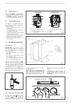
installed. However, suitable clearances
for maintenance and servicing should be
provided, see fig. 1.
Ventilation requirements for 100 BFR boi-
lers and cascade systems
.
BS6644:2005 has a requirement that the
temperatures in a room or compartment
do not exceed certain levels:
– 25°C at floor level (0-100 mm)
– 32°C at mid level (1.5 M above the floor
level)
– 40°C at ceiling level (0-100 mm from
ceiling)
The following is provide for your guidance
only, and assumes the ventilation air is
taken directly from outside. The sizes of the
vents may need to be increased in respect
of other appliances installed in the same
area, and seasonal use. Take care that the
position of low level vents would not subject
to adverse weather conditions, ie flooding.
When installed as a class B appliance
(open flued, not roomed sealed).
Installed in a room
High level (within 15% of the room height
from ceiling) - 2 cm
2
/KW of net heat input
Low level (low as possible within 1 metre
from floor natural gas, 250 mm LPG)– 4
cm
2
/KW of net heat input. Therefore a sin-
gle
60 BFR
(58 KW net input) boiler would
require 116 cm
2
at high level and 232 cm
2
at low level. A single
100 BFR
(98 KW net
input) boiler would require 196 cm
2
at high
level and 392 cm
2
at low level.
Installed in a compartment or enclosure
High level (within 15% of the room height
from ceiling) - 5 cm
2
/KW of net heat input.
Low level (low as possible within 1 metre
from floor natural gas, 250 mm LPG) – 10
cm
2
/KW of net heat input.
Therefore a single
60 BFR
(58 KW net
input) boiler would require 290 cm
2
at high
level and 580 cm
2
at low level.
A single
100 BFR
(98 KW net input) boiler
would require 490 cm
2
at high level and
980 cm
2
at low level.
When installed as a class C appliance
(room sealed)
Installed in a room
High level (within 15% of the room height
from ceiling) - 2 cm
2
/KW of net heat input
Low level (low as possible within 1 metre
from floor natural gas, 250 mm LPG)– 2
cm
2
/KW of net heat input
Therefore a single
60 BFR
(58 KW net
input) boiler would require 116 cm
2
at high
level and 116 cm
2
at low level.
A single
100 BFR
(98 KW net input) boiler
would require 196 cm
2
at high level and
196 cm
2
at low level.
Installed in a compartment or enclosure
High level (within 15% of the room height
from ceiling) - 5 cm
2
/KW of net heat input
Low level (low as possible within 1 metre
from floor natural gas, 250 mm LPG)– 5
cm
2
/KW of net heat input.
Therefore a single
60 BFR
(58 KW net
input) boiler would require 290 cm
2
at high
level and 290 cm
2
at low level.
A single
100 BFR
(98 KW net input) boiler
would require 490 cm
2
at high level and
490 cm
2
at low level.
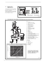
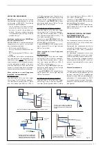
CONDENSATE DISPOSAL POSITIONING
AND TERMINATION OF THE
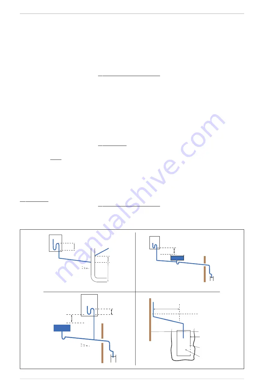
CONDENSATE DRAIN PIPE (fig. 22)
The condensate pipe should run and termi-
nate internally to the house soil and vent
stack or waste pipe.
Alternatively, the condensate can be dis-
charged into the rainwater system, or into a
purpose-made soak away (condensate
absorption point).
An alternative condensate waste pipe
should be considered where the system
could be effected by extreme weather con-
ditions. All connecting drainage pipework
should have a fall of at least 2.5° to the hor-
izontal, or approximately 50 mm per metre
of pipe run.
Material for condensate
The condensate drainage pipe should be run
in a standard drain pipe material, e.g. PVC
(polyvinyl chloride), PVC-U (unplasticised
polyvinyl chloride), ABS (acrylonitrile-butadi-
enestyrene), PP (polypropylene) or PVC-C
(crosslinked polyvinyl chloride). The conden-
sate drain can be attached to the syphon
(see figures).
31
Pipe slope
>2
1
/
2
deg
Internal trap
>75mm
>110mm
(for 100mm stack)
> 450mm
(for up to 3 floors)
100mm Internal stack
Branch
pipe
SINK
Height above
sink >100mm
Internal trap
>75mm
Pipe slope
>2
1
/
2
deg
Height above
sink >100mm
SINK
> 1m
Section of plastic
drain pipe
Holes in side away
from dwelling
Ground level
Alternative
ground level
Limestone
chipping fill
Internal termination of condensate drainage pipe to internal stack
External termination of condensate
drainage pipe via internal discharge
branch (e.g. sink waste) and condensate
syphon
External termination of condensate
drainage pipe via internal discharge
branch (e.g. sink waste - proprietary
fitting) and condensate syphon
External termination of
condensate drainage
pipe to absorpion point
Fig. 22
Summary of Contents for Planet Dewy 100 BFR
Page 3: ......
Page 29: ...29 For 100 BFR and boilers in cascade ...
Page 30: ...30 ...
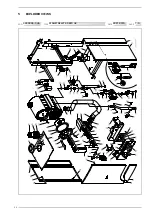
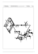
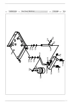
Page 32: ...32 5 EXPLODED VIEWS COD TYPE DATE PAGE 3830005 345 PLANET DEWY 60 BFR UK 20 01 2010 1 4 ...
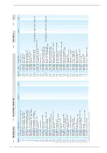
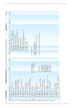
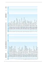
Page 33: ...33 COD TYPE DATE PAGE 3830005 345 PLANET DEWY 60 BFR UK 20 01 2010 2 4 ...
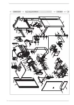
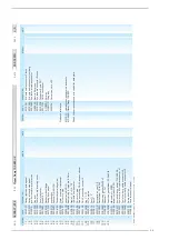
Page 36: ...36 COD TYPE DATE PAGE 3830037 212 Planet Dewy 100 BFR UK 20 01 2010 1 4 ...
Page 37: ...37 COD TYPE DATE PAGE 3830037 212 Planet Dewy 100 BFR UK 20 01 2010 2 4 ...

