11
being trapped in the pipe, the number of
bends should be kept to a minimum.
Pipework must be angled down from the
boiler with a fall of at least 2.5°.
The pipework must be supported at a dis-
tance of 0.5 m for inclined runs and 1.0 m
for vertical runs.
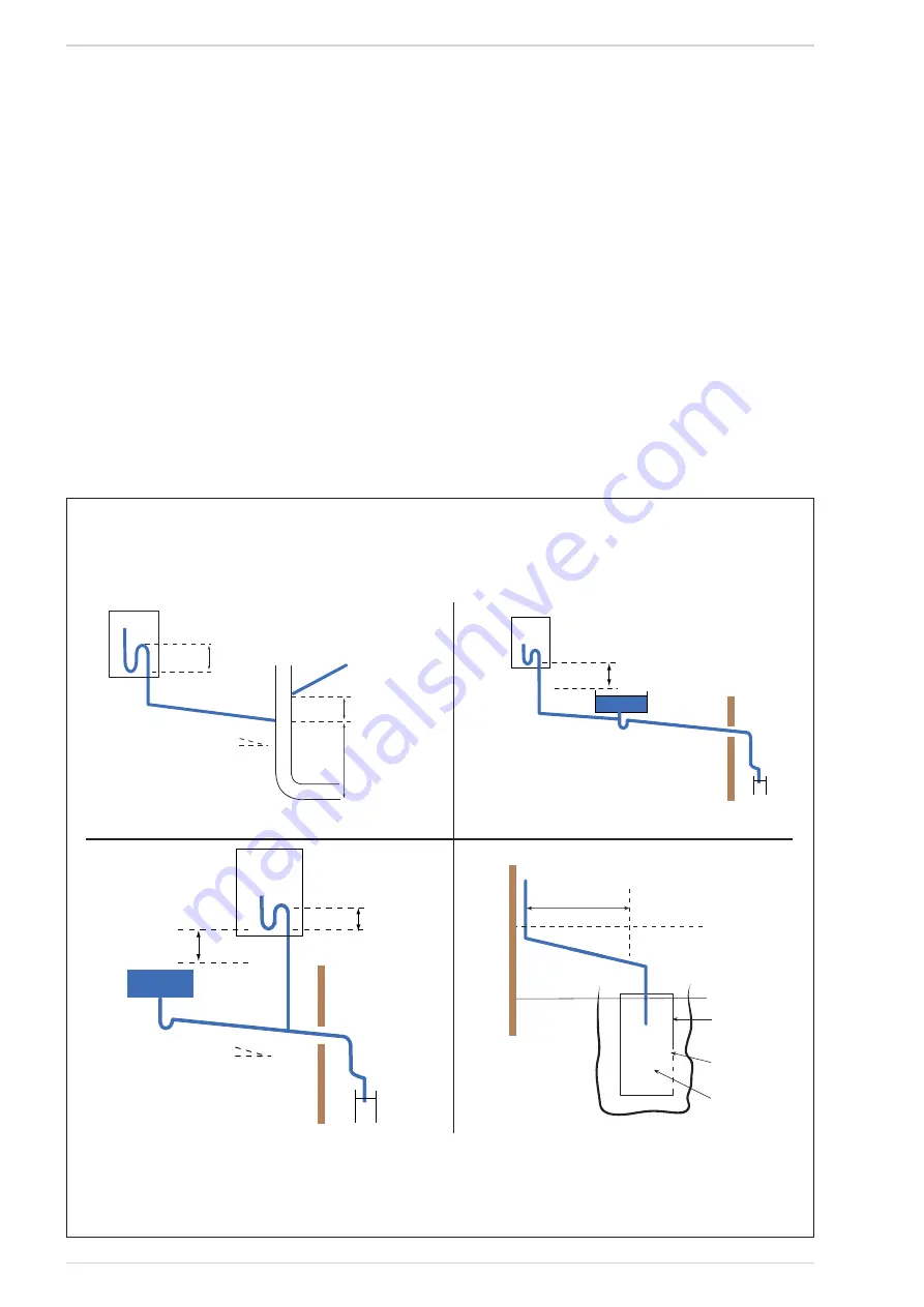
Condensate traps
Where the condensate drain is not sealed
to the discharge connection a trap will be
required. The water seal should be 38 mm
or more for external discharge and 75 mm
or more for internal discharge. When con-
necting to a external stack the trap should
be located within the building.
Stack pipes
Condensate connections should be at least
450 mm above any bend at the bottom of a
stack pipe in a single or multi-story dwelling
up to 3 storeys. There are specific require-
ments when connecting to a stack pipe
serving multi-storey buildings greater than
3 storeys.
All connections to stack pipes should avoid
across flow between other Branch pipes.
Soakaways
Any soakaways have to be purpose-made
and located as close to the boiler as possi-
ble, but clear of the buildings foundations
and any buried services. The best option is
to purchase a soakaway from a drainage
manufacturer and install it to the manufac-
turers recommendation.
Condensate disposal positioning and ter-
mination of the condensate drain pipe
The condensate pipe should run and termi-
nate internally to the house soil and vent
stack or waste pipe. Alternatively, the con-
densate can be discharged into the rainwa-
ter system, or into a purpose-made soak
away (condensate absorption point).
An alternative condensate waste pipe
should be considered where the system
could be effected by extreme weather con-
ditions. All connecting drainage pipework
should have a fall of at least 2.5° to the hor-
izontal, or approximately 50 mm per metre
of pipe run.
2.3.2
Requirements for
sealed water systems
The heating system design should be based
on the following information:
a) The available pump head is given in fig. 12.
b) The burner starts when the C.H. flow
reaches 400÷450 l/h. This safety con-
dition is ensured by the flow switch.
Pipe slope
>2
1
/
2
deg
Internal trap
>75mm
>110mm
(for 100mm stack)
> 450mm
(for up to 3 floors)
100mm Internal stack
Branch
pipe
SINK
Height above
sink >100mm
Internal trap
>75mm
Pipe slope
>2
1
/
2
deg
Height above
sink >100mm
SINK
> 1m
Section of plastic
drain pipe
Holes in side away
from dwelling
Ground level
Alternative
ground level
Limestone
chipping fill
Internal termination of condensate drainage pipe to internal stack
External termination of condensate
drainage pipe via internal discharge
branch (e.g. sink waste) and condensate
syphon
External termination of condensate
drainage pipe via internal discharge
branch (e.g. sink waste - proprietary
fitting) and condensate syphon
External termination of
condensate drainage
pipe to absorpion point
Fig. 4/a


