12
with a slope of at least 5 mm per metre to
ensure drainage of condensation water.
The plastic pipes normally used for civil
drains are the only type of pipe which is
appropriate for conveying condensation
to the building’s sewer pipes.
2.4.6
Filter on the gas pipe
The gas valve is supplied ex factory with an
inlet filter, which, however, is not adequate to
entrap all the impurities in the gas or in gas
main pipes. To prevent malfunctioning of the
valve, or in certain cases even to cut out the
safety device with which the valve is equip-
ped, install an adequate filter on the gas pipe.
2.4.7
Discharge Pipe
See fig. 6 for example discharge pipe termi-
nations.
2.5
FILLING AND COMMISSIONING
2.5.1 D.H.W.
circuit
Before filling the D.H.W. system, ensure
appliance selector knob is in the “Off” posi-
tion, then open the hot water tap nearest
the appliance. Open the D.H.W. supply isola-
ting valve to the appliance, once water
starts to flow from the tap close it, and then
open and close each hot water tap in turn
to ensure that all the air is removed from
the pipework. Open the hot water tap
furthest away from the appliance and let
water flow for about 10 minutes, or for suf-
ficient time to flush out the system. Check
for leaks.
2.5.2 C.H.
circuit
Once the D.H.W. circuit is commissioned
the C.H. circuit can be filled via the external
filling loop. Ensure both the D.H.W. and C.H.
temperature controls are set to minimum,
and that there is no room thermostat
demand. Turn on the electrical supply
to the appliance, (see Section 2.10), and
turn the selector knob to the summer posi-
tion. Open the filling loop’s C.H. isolating
valve and then the D.H.W. double check iso-
lating valve (See fig. 2 & 5/a).
Once the green
“1 bar”
led lights up close
both isolating valves, and disconnect the
flexible hose from the D.H.W. double check
isolating valve. Check for leaks and free
rotation of the circulating pumps. The
appliance can then be commissioned by fol-
lowing the User Instructions.
2.6
COAXIAL DUCT ø 60/100
The air inlet-smoke outlet assembly, code
8096250, is included in the standard sup-
ply of the appliance complete with mounting
instructions.
2.6.1
Coaxial duct accessories
The accessories to be used for this type of
installation and some of the connecting
systems that may be adopted are illustred
in fig. 7.
With the pipe bend included in the
kit, the maximum length of the piping
should not exceed 4.6 meter.
When the
vertical extension code 8086950 is used,
the terminal part of the pipe must always
come out horizontally.
2.6.2
Positioning the outlet terminals
The outlet terminals for forced-draught
appliances may be located in the external
perimeter walls of the building.
To provide some indications of possible solu-
tions,
Table 1
gives the minimum distances
to be observed, with reference to the type
of building shown in fig. 8.
2.7
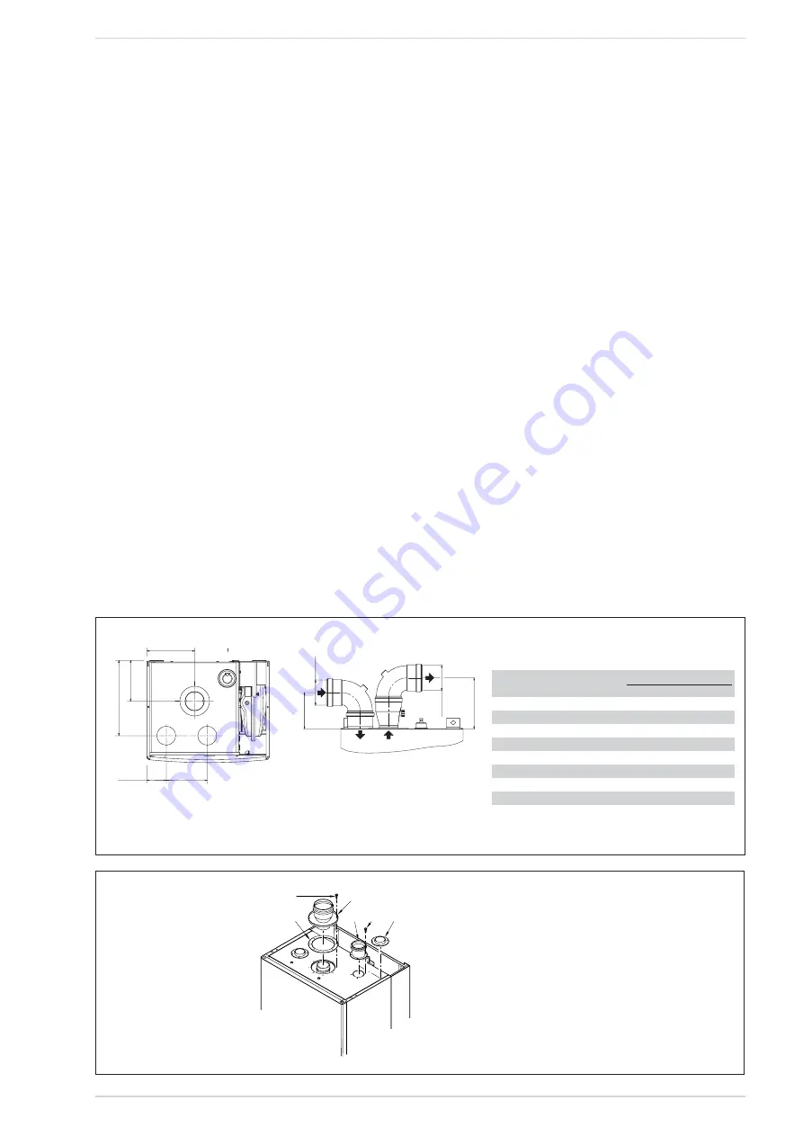
SEPARATE PIPES ø 80
A special kit may be used to separate the
flue gas outlet from the fresh air intake.
The intake may be installed to the right or
left of the flue gas outlet.
1
2
3
4
5
3
Fig. 10
KEY
1
Blind flange
2
Flue gas duct flange
3
Fixing screw
4
Gasket ø 125/95
5
Intake duct collar
Fig. 9
156,5
13
3
24
6
63,5
134
CS
CA
CA
11
8
Ø 80
Ø 80
16
6
KEY
CA
Inlet
CS
Outlet
TABLE 2
Accessories ø 80
Head loss (mm H
2
O)
Inlet
Outlet
Roof outlet
90° elbow MF
0.30
0.50
–
45° elbow MF
0.20
0.40
–
Extension L. 1000 (horizontal)
0.20
0.40
–
Extension L. 1000 (vertical)
0.30
0.30
–
Outlet terminal
–
0.40
–
Inlet terminal
0.10
–
–
Doubler fitting
0.30
–
–
Roof outlet terminal L. 1381
–
–
0.60


